Energy emission device

a technology of energy emission and emission chamber, which is applied in the direction of contraceptive devices, diagnostic recording/measuring, therapy, etc., can solve the problems of difficult to prevent accumulation and deposition of a, further remove accumulated a, and no fundamental treatment for alzheimer's disease has been established, so as to achieve efficient promotion of csf flow, high efficiency, and saving consumed energy

Active Publication Date: 2018-09-13
HITACHI LTD
View PDF3 Cites 3 Cited by
  • Summary
  • Abstract
  • Description
  • Claims
  • Application Information

AI Technical Summary

Benefits of technology

[0011]According to the present invention, by emitting energy in accordance with the sleep depth during sleep in which waste discharge has a highest efficiency, it is possible to deliver energy to the cerebrospinal fluid and / or the brain cell interstitial fluid without interfering with the sleep and while saving consumed energy. Furthermore, emitting energy in accordance with the sleep depth or emitting energy while monitoring the body temperature, deep body temperature or skin temperature provides an effect of avoiding interference with a comfortable sleep. Furthermore, emitting energy in accordance with a CSF flow passage allows an effect of being able to efficiently promote the CSF flow to be expected. Promoting the CSF flow in this way provides an effect of eliminating (preventing) blocking of the CSF flow and is effective in prevention and treatment of Alzheimer's disease and other diseases.

Problems solved by technology

However, no fundamental treatment for Alzheimer's disease has been established yet and the problem is that there is no choice but to depend on symptomatic treatment and symptomatic improvement therapy.
As described above, although accumulation, outside brain cells, of amyloid beta (Aβ) protein produced in the brain cells is believed to be one of causes of Alzheimer's disease, it is difficult to prevent accumulation and deposition of Aβ and further remove accumulated Aβ.

Method used


Image

  • Energy emission device
  • Energy emission device
  • Energy emission device

Examples


example 1

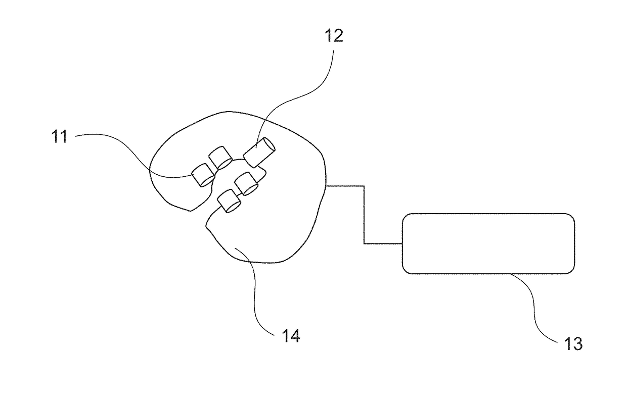
[0044]FIG. 1 shows a conceptual diagram illustrating a neck pillow type energy emission device. The energy emission device is supposed to be worn around the neck of a subject. A cushion part 14 is made of an elastic material and an energy emission section 11 is attached to the skin around the neck of the subject. The energy emission section 11 may be an energy emission means set in contact with or nearly in contact with, for example, the skin of the subject such as a light source, for example, a laser diode (LD), a light-emitting diode (LED) or a piezoelectric transducer or an ultrasonic transducer. The energy emission device further comprises an energy control section 13 for controlling energy emission timing or emission intensity. The energy control section 13 controls energy emission timing or emission intensity depending on a sleeping state detected by a sleeping state detection section 12. Such a configuration allows energy emission to be efficiently performed during sleep with...

example 2

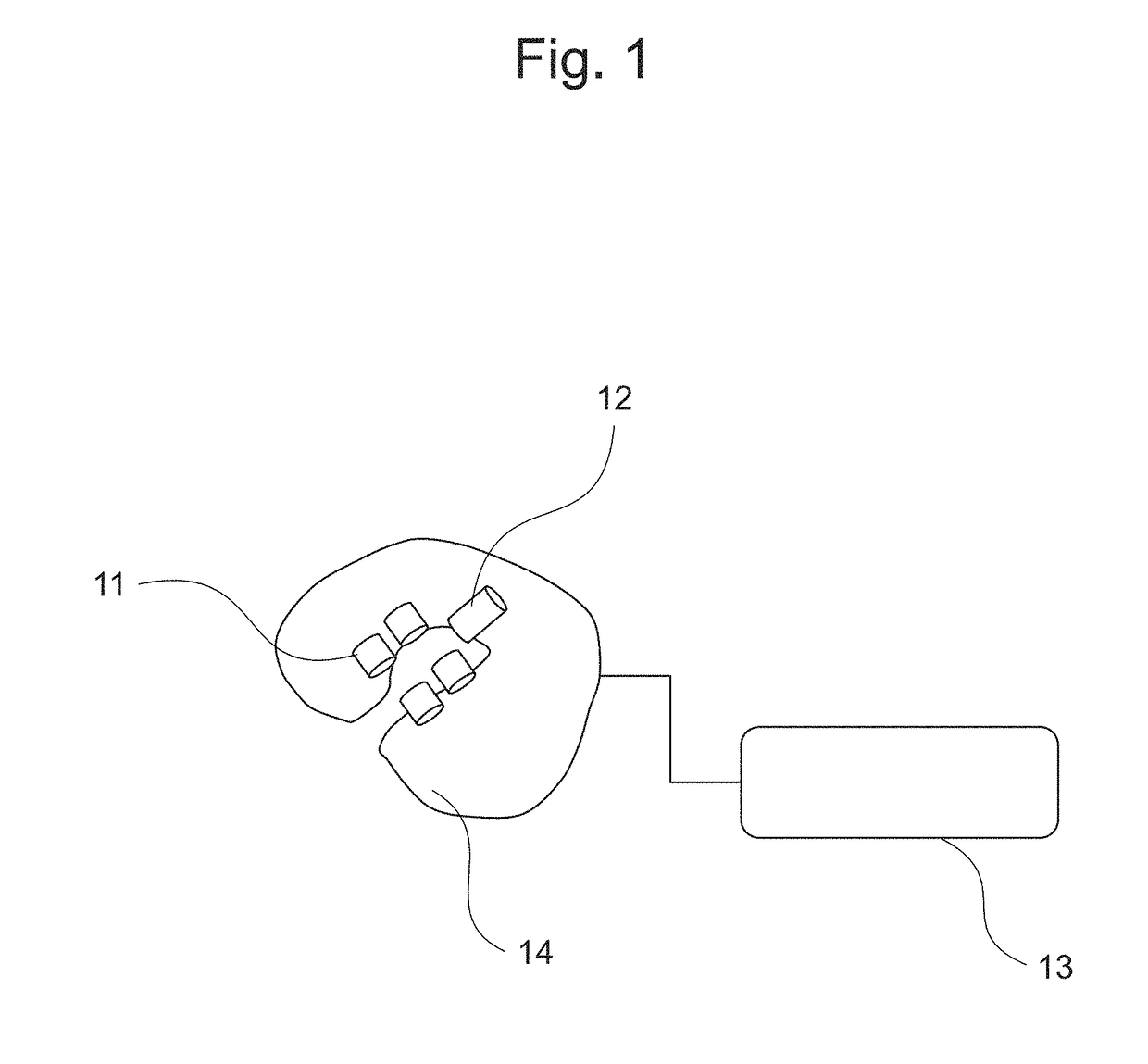
[0048]FIG. 2 shows a conceptual diagram of a neck pillow type energy emission device that controls emission energy depending on ambient light environments detected by an optical sensor. The energy emission section 11 and the cushion part 14 are arranged for purposes similar to those of Example 1 (FIG. 1). An optical sensor 20 is configured to measure ambient light environments and the energy control section 13 is configured to operate only when the ambient light intensity acquired by the optical sensor 20 is lower than a predetermined value or to automatically start operating when the ambient light intensity is smaller than a predetermined value. When the device of the present invention is used, the subject is instructed that the subject is placed, for example, in a dark environment. In such a case, the optical sensor 20 plays a role as an ON / OFF switch of the device of the present invention. When there is bright ambient, if it is not the right time for energy emission according to ...

example 3

[0049]FIG. 3 is a flowchart showing emission of energy while monitoring wakefulness or a sleeping state of the subject, a state of the subject and a state of the cerebrospinal fluid (CSF). After a start, wakefulness or a sleeping state of the subject is measured (step S301). It is determined whether the sleeping state level is equal to or higher than a predetermined value or whether the wakefulness level is equal to or lower than a predetermined value (step S302). It is determined whether the non-REM sleep is in stage 3 or 4 (deepest level). When “Yes” in step S302, energy emission is started (step S303). The states of the subject and the cerebrospinal fluid (CSF) are measured (step S304). For example, it may be determined whether a body temperature measured by a body thermometer, a skin temperature measured by a skin thermometer, a perspiration state measured by a perspiration meter or a cerebrospinal fluid flow measured by a cerebrospinal fluid flow monitor falls within a predeter...


PUM


Abstract

The present invention provides an energy emission device comprising: one or a plurality of energy emission means for emitting at least one type of energy selected from the group consisting of an electromagnetic wave or an electromagnetic stimulation, an elastic wave, an oscillatory wave and heat to at least one position of a subject selected from the group consisting of the brain, the spinal cord, the cerebrospinal fluid or the flow passage thereof and the brain cell interstitial fluid or the flow passage thereof; an energy controlling means for controlling an amount of energy emitted from the energy emission means; and a means for obtaining information relating to wakefulness and / or a sleeping state of the subject, in which the energy controlling means controls the amount of energy emitted depending on the information relating to the wakefulness and / or the sleeping state.

Description

TECHNICAL FIELD[0001]The present invention relates to an energy emission device and a method for controlling flow rates of the cerebrospinal fluid and / or the brain cell interstitial fluid by emitting energy such as electromagnetic wave, oscillation, ultrasound (acoustic) to an interior of a living body.BACKGROUND ART[0002]Alzheimer's disease which is one of neurodegenerative diseases is said to account for a highest percentage, exceeding approximately 60%, among causative diseases of dementia. Examples of symptoms of Alzheimer's disease include memory impairment, impaired linguistic ability or judgment, problematic behavior such as wandering, depressive symptoms, consciousness muddle, hallucinations, illusion, and delusion.[0003]However, no fundamental treatment for Alzheimer's disease has been established yet and the problem is that there is no choice but to depend on symptomatic treatment and symptomatic improvement therapy. On the other hand, proportion of elderly people is estim...

Claims


Application Information

Patent Timeline
Patent Type & Authority Applications(United States)
IPC IPC(8): A61N2/00A61N2/02A61N5/06A61N7/00A61F7/00A61B5/00A61B5/0205
CPCA61N2/002A61N2/02A61N5/06A61N2/006A61N7/00A61F7/00A61B5/4809A61B5/4836A61B5/02055A61B5/742A61N2005/0651A61N2005/067A61N2007/0026A61F2007/0024A61B5/01A61B5/024A61B5/031A61B5/032A61B5/0476A61B5/0077A61B5/1077A61B5/11A61B5/14507A61B5/4064A61B5/407A61B5/4812A61B2560/0242A61N2007/0039A61N2007/0091A61H23/00A61H2201/0134A61H2201/0149A61H2201/1609A61H2201/50A61B5/369A61N5/067A61H23/02
Inventor FUNANE, TSUKASASATO, HIROKI
Owner HITACHI LTD
Why Eureka
Try Eureka