

Switched reluctance motor modeling method
- Summary
- Abstract
- Description
- Claims
- Application Information
AI Technical Summary
Benefits of technology
Problems solved by technology
Method used
Image

Examples
Embodiment Construction
[0015]Hereunder the present invention will be detailed in an embodiment with reference to the accompanying drawings.
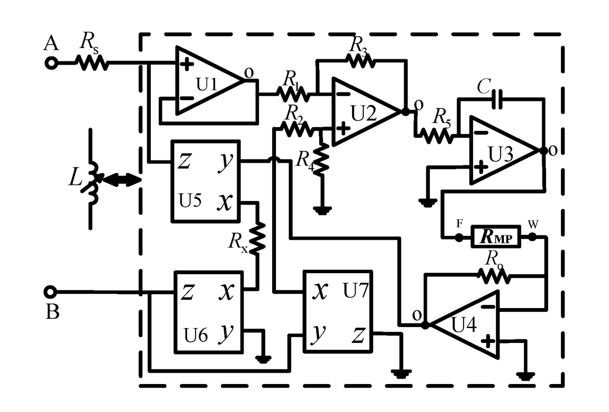
[0016]As shown in FIG. 1, the modeling method for switched reluctance motor according to the present invention uses four operational amplifiers U1, U2, U3 and U4, three current conveyors U5, U6 and U7, a variable resistor RMP composed of a digital potentiometer and a digital controller, eight resistors R1, R2, R3, R4, R5, RO, RX and RS, and a capacitor C, the input ports are A and B respectively;
[0017]the modeling method comprises:
[0018]connecting the input port A with a non-inverting input port of the operational amplifier U1 and a port z of the current conveyor U5 via the resistor RS respectively, connecting the input port B with a port z of the current conveyor U6 and a port y of the current conveyor U7 respectively, connecting an output port 0 of the operational amplifier U1 with an inverting input port of the operational amplifier U1 and one port of the resistor R...
PUM
 Abstract
Description
Claims
Application Information