
Multi plate screw press sludge dewatering machine

a screw press and sludge dewatering technology, applied in the field of sludge dewatering, can solve the problems of low safety coefficient, high speed reduction ratio, heavy and inconvenient maintenance, etc., and achieve the effect of reducing the phenomenon of shaft blockage and shaft sticking of sludge, reducing the work efficiency of the dewatering equipment, and reducing the number of shafts

Active Publication Date: 2018-12-06
SHANGHAI TECHASE ENVIRONMENT PROTECTION
View PDF0 Cites 22 Cited by
  • Summary
  • Abstract
  • Description
  • Claims
  • Application Information

AI Technical Summary

Benefits of technology

The patent aims to improve the performance of a multi plate screw press dewatering machine by expanding its application range and increasing the solid content of the treatable raw water. It also introduces a triangular lug boss structure for the fixed rings, which enhances stability and support area, controls deformation, and improves the bending performance of the fixed rings.

Problems solved by technology

4: A helical bevel gear speed reducer and a worm-gear or gear speed reducer are usually adopted to provide driving power for the helical shaft, and are relatively high in speed reduction ratio, low in safety coefficient, heavy and inconvenient to maintain.
5: A lamination (movable rings and fixed rings) of the existing multi plate screw press sludge dewatering machine is mainly made from a metal material such as 304 stainless steel, the metal material such as the 304 stainless steel is poor in abrasion resistance and corrosion resistance, and its service life is usually about 1 year, so that an application range and service life of the multi plate screw press sludge dewatering machine are limited, requirements on the service life and performance of the equipment cannot be met, and a requirement of a user may not be met.

Method used


Image

  • Multi plate screw press sludge dewatering machine
  • Multi plate screw press sludge dewatering machine
  • Multi plate screw press sludge dewatering machine

Examples


embodiment 1

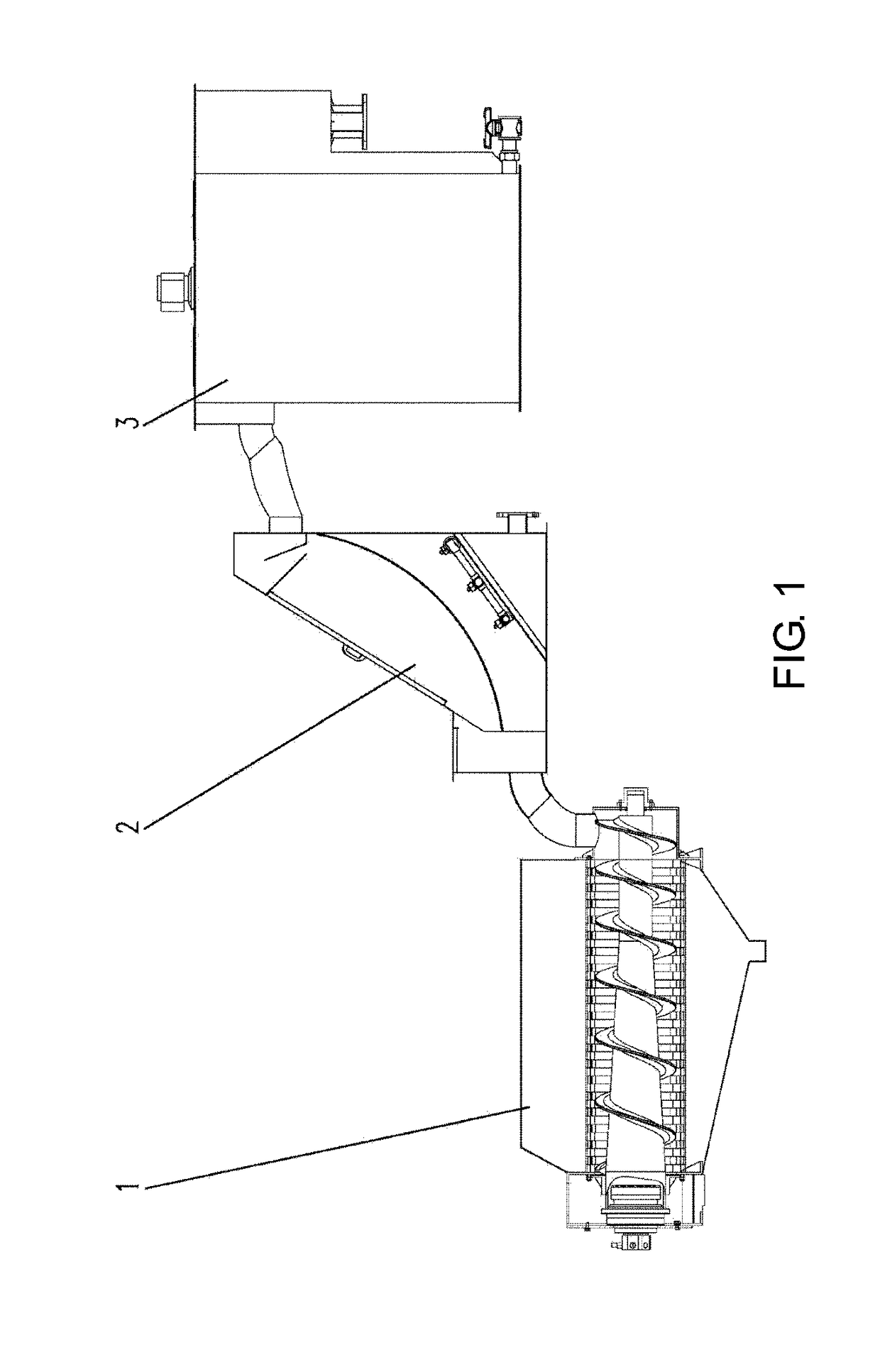
[0064]As shown in FIG. 1, multi plate screw press sludge dewatering machine of the present invention in the present embodiment includes a flocculation mixing part 3, a rapid filtering part 2 and a multi plate screw press sludge dewatering part 1 which are sequentially connected, and is an integrated machine combining the foregoing three parts.

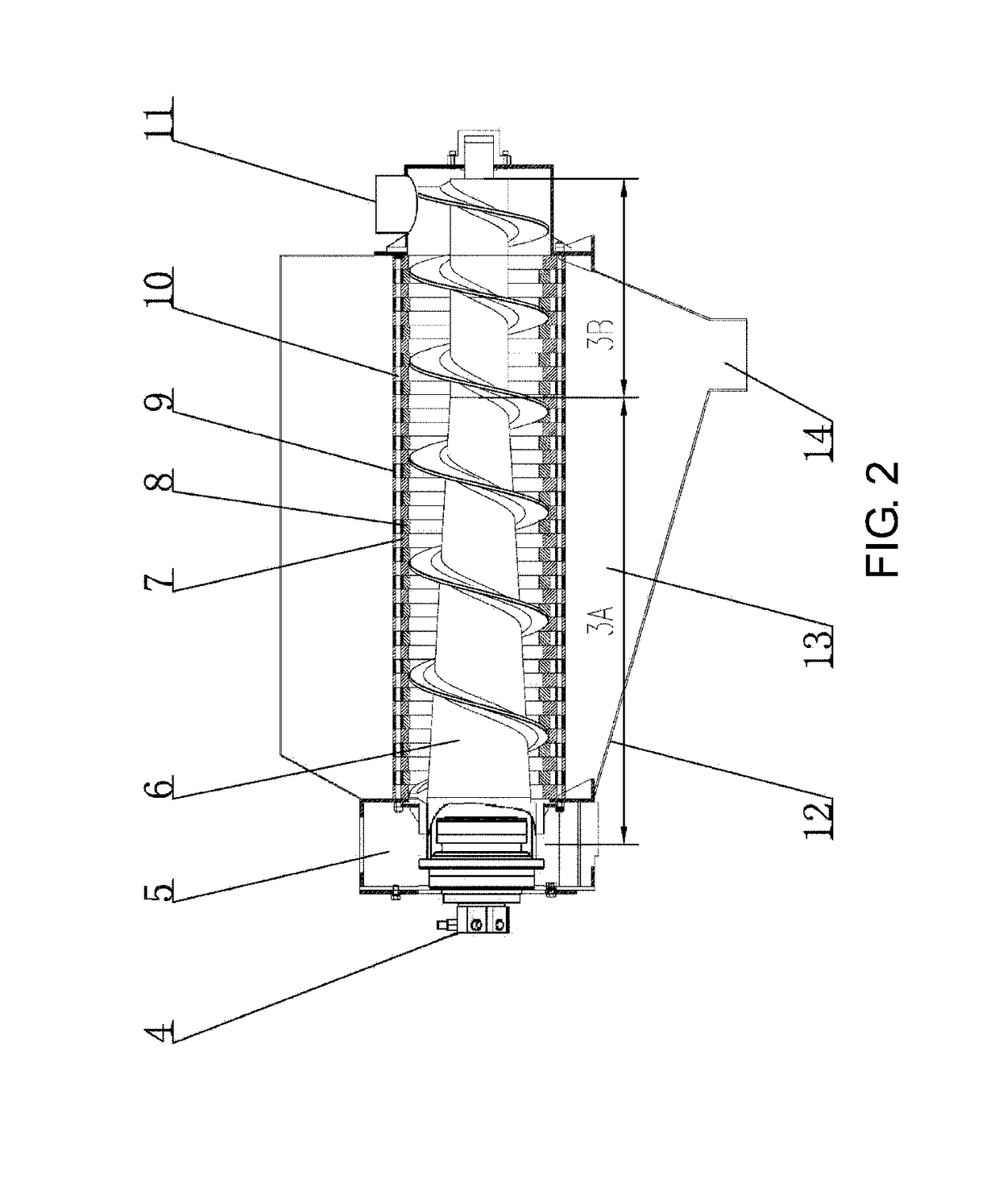
[0065]As shown in FIG. 2, the multi plate screw press sludge dewatering part 2 includes components such as a power driving device 4, a sludge discharging tank 5, a helical shaft 6, fixed rings 7, movable rings 8, regulation blocks 9, connecting rods 10, a sludge inlet tank 11, a housing 12, a filtrate collection tank 13 and a filtrate outlet opening 14; the plurality of fixed rings 7 are sequentially arranged in the housing 12, one movable ring 8 is arranged between every two adjacent fixed rings 7, and one regulation block 9 is arranged between every two adjacent fixed rings 7 to regulate a gap between the two fixed rings, so as to enable the ...

embodiment 2

[0080]Multi plate screw press sludge dewatering machine of the present invention in the present embodiment is basically the same as that in embodiment 1, and the difference is as follows.

[0081]As shown in FIG. 9, FIG. 10, FIG. 11 and FIG. 12, each fixed ring 7 of the multi plate screw press sludge dewatering machine of the embodiment consists of an annular main body and six fixing lugs 71 extending from the annular main body along a circumferential direction, and a small fixing hole 73 is formed in each fixing lug 71; and a circular lug boss 72 protruding outwards perpendicularly to the circumferential direction is further arranged at each fixing lug 71, and a small fixing hole 73 corresponding to the small fixing hole 73 in each fixing lug is also formed in each circular lug boss 72. According to the present embodiment, an injection molding or compression molding process is adopted, regulation blocks 9 are integrated with the fixed rings 7 by virtue of a mold, and the regulation bl...

embodiment 3

[0085]Multi plate screw press sludge dewatering machine of the present invention in the present embodiment is basically the same as that in embodiment 1, and the difference is as follows.

[0086]As shown in FIG. 13, FIG. 14, FIG. 15 and FIG. 16, each fixed ring 7 of the multi plate screw press sludge dewatering machine of the present embodiment consists of an annular main body and eight fixing lugs 71 extending from the annular main body along a circumferential direction, and a small fixing hole 73 is formed in each fixing lug 71; the eight fixing lugs 71 are triangular; a triangular lug boss 75 protruding outwards perpendicularly to a circumferential direction is further arranged at each fixing lug 71, and a small fixing hole 73 corresponding to the small fixing hole 73 in each fixing lug is also formed in each triangular lug boss 75. According to the present embodiment, an injection molding or compression molding process is adopted, regulation blocks 9 are integrated with the fixed ...


PUM

PropertyMeasurementUnit
thicknessaaaaaaaaaa
thicknessaaaaaaaaaa
roughnessaaaaaaaaaa

Abstract

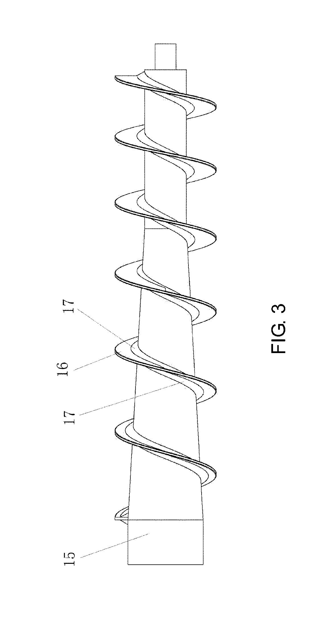
The present invention provides a multi plate screw press sludge dewatering machine and a helical shaft thereof. The multi plate screw press sludge dewatering machine includes fixed rings, movable rings, the helical shaft, a sludge inlet tank and a sludge discharging tank; the helical shaft adopts a variable diameter variable pitch helical shaft, a lead angle arrangement sequence of a helical blade of the whole helical shaft is gradual reduction from the sludge discharging tank to the sludge inlet tank, and the lead angle arrangement sequence is gradually reduced from 16°-22° to 6°-14°; a pitch of the helical shaft is gradually increased along a direction from the sludge inlet tank to the sludge discharging tank; a diameter of a shaft body of the helical shaft is gradually increased along with a direction of the sludge discharging tank from a ⅓ position of a shaft length; and blockage prevention plates are arranged on two sides of the bottom of the helical blade. The helical shaft in the present invention is specially designed, so that the pitch is more reasonable, a helical angle is gentler, frictional resistance when sludge passes through the helical shaft may be effectively reduced, and phenomena of shaft blockage and shaft sticking of the sludge may be reduced.

Description

CROSS-REFERENCE TO RELATED APPLICATION[0001]This is a continuation of International Application No. PCT / CN2017 / 073970, filed on Feb. 17, 2017, which claims the priority benefits of China Application No. 201620133263.4, filed on Feb. 22, 2016 and China Application No. 201610256982.X, filed on Apr. 22, 2016. The entirety of each of the above-mentioned patent applications is hereby incorporated by reference herein and made a part of this specification.BACKGROUND OF THE INVENTION1. Field of the Invention[0002]The present invention belongs to the technical field of sludge dewatering and relates to multi plate screw press sludge dewatering machine.2. Description of Related Art[0003]Multi plate screw press sludge dewatering machine is a filtering driving device formed by stacking fixed rings and movable rings through which a helical shaft penetrates. Its front end is a concentration portion and its rear end is a dewatering portion. Filtering gaps formed between the fixed rings and the mova...

Claims


Application Information

Patent Timeline
Patent Type & Authority Applications(United States)
IPC IPC(8): C02F9/00B01D29/01B01D29/68B01D29/46B01D29/90B01D36/02C08L71/02C08J5/00
CPCC02F9/00B01D29/014B01D29/68B01D29/46B01D29/90B01D36/02C08L71/02C08J5/005C02F11/125C02F11/122C02F1/004C02F1/5281C02F2303/16B01D2201/282B01D2201/48B29C45/0001B29K2105/12B29K2307/04B29K2259/00C08J2371/02C08J2427/18B01D29/035B01D29/356B01D29/56B01D29/6476C08L59/02C02F11/14C02F2303/14B30B9/121C08K7/06C08L27/18
Inventor SUN, GANGFANLIU, DAOGUANGZHANG, WENBIAO
Owner SHANGHAI TECHASE ENVIRONMENT PROTECTION
Learn More