Low-level laser light therapy devices, and methods of use

a laser light therapy and low-level technology, applied in the field of low-level laser light therapy devices, and methods of use, can solve the problems of signal processing decisions, design choices, signal processing decisions, electronic component requirements, and large power consumption, and achieve the effects of low power consumption, convenient use, and low cos

Inactive Publication Date: 2018-12-27
TICHAUER TECHNICAL LAB LLC
View PDF1 Cites 3 Cited by
  • Summary
  • Abstract
  • Description
  • Claims
  • Application Information

AI Technical Summary

Benefits of technology

[0021]The devices described herein can be used to deliver LLLLT, are easy to use, and require low power consumption. Additionally, the device can be light-weight, portable, and mass produced at a minimal per-unit cost.

Problems solved by technology

Traditional LLLLT techniques rely on lasers and light emitting diodes (LEDs) that consume a significant amount of power.
Among the causes for substantial power consumption are signal processing decisions, design choices, and electronic component requirements.

Method used


Image

  • Low-level laser light therapy devices, and methods of use
  • Low-level laser light therapy devices, and methods of use
  • Low-level laser light therapy devices, and methods of use

Examples


example 1

tion Of Therapeutic Effects Of LLLLT On Facial Scarring

[0139]The healing rate of two closely located stitches has been observed. Referring to FIG. 5, the image of an upper stitch 310 and a lower stitch 320 can be seen above and below the right eye of a patient. LLLLT was directed to the lower stitch 320 for approximately three minutes per day for a period of one month beginning the day after surgery. Treatment on the upper stitch 310 was delayed for a period of six days and then applied equally with the lower stitch 320. LLLLT on the upper stitch 310 ended on the same day as the lower stitch 320.

[0140]FIGS. 5(a)-5(f) present images of the contrast in healing between the upper stitch 310 and the lower stitch 320 during the first six days after surgery. FIG. 5(a) presents an image of the upper stitch 310 and the lower stitch 320 one day after surgery. FIG. 5(b) presents an image of the upper stitch 310 and the lower stitch 320 two days after surgery. The lower stitch 320 appears to be...

example 2

tion Of Therapeutic Effects Of LLLLT On Eye Injury

[0142]A subject's right eye was injured due to exposure to a dose of ultraviolet UV light. The vision in the right eye got cloudy and the color perception between the right eye and the left eye differed. In addition the perceived size of objects seemed to differ between the two eyes.

[0143]The left eye was exposed to a red colored LED, with the eyelid closed. Visible red light could be seen through and illuminating the eyelid. With the exception of certain positions of the LED relative to the right eye, the right eye had difficulty in perception of the red light. The right eye was exposed to periodic exposures of light from a red colored LED. Improvements to the right eye were noted on a daily basis. Within six months, the right eye appeared to be 90% healed. After six months of daily exposures to the red colored LEDm the perception of the left eye and the right eye are almost identical.


PUM


Abstract

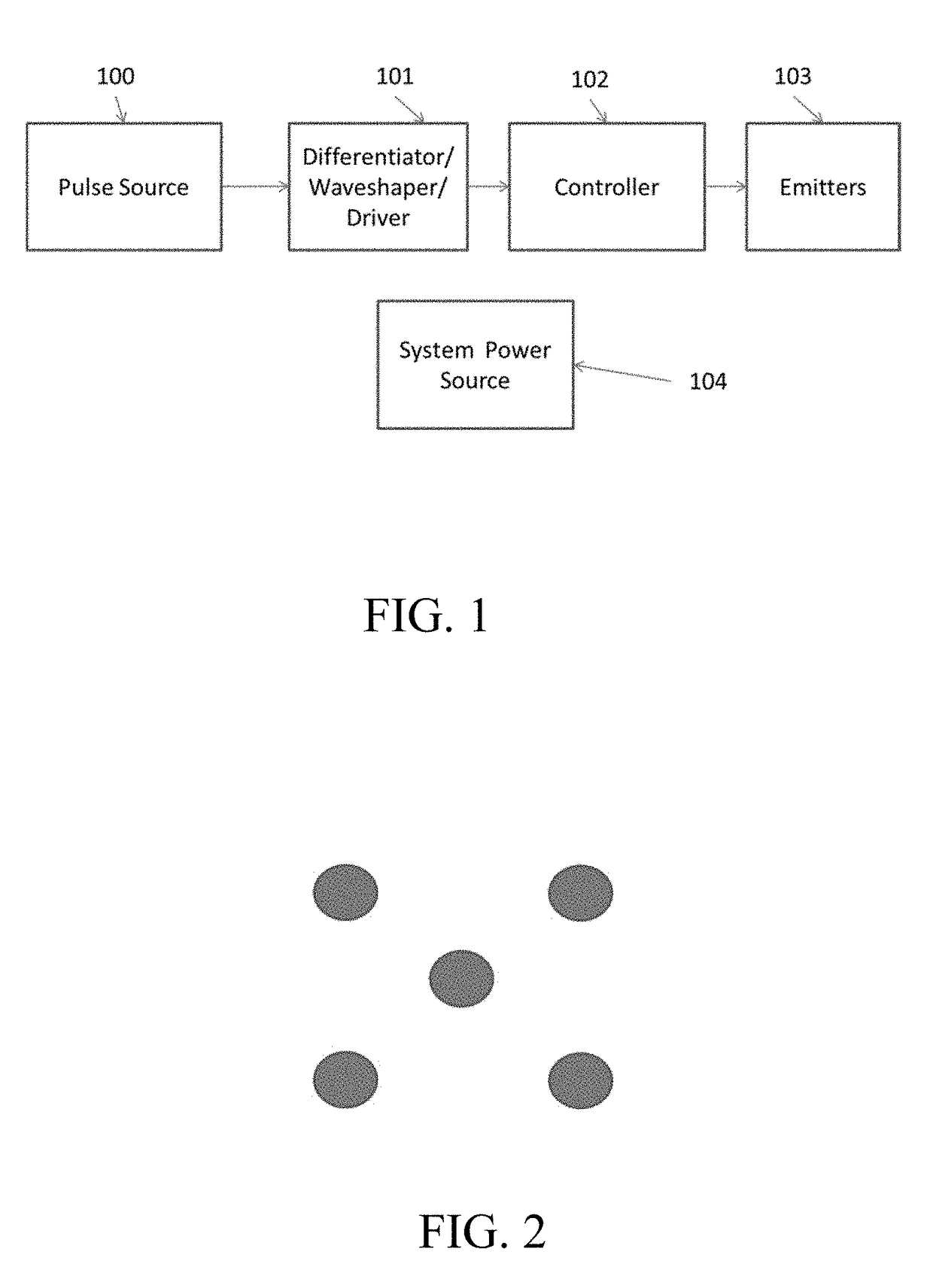
Devices and methods for low-level laser light therapy for animals and plants are provided. A device can include a pulse generator configured to generate a pulse train, wherein a pulse wave of the pulse train is configured to have a rectangular, non-sinusoidal waveform and a duty cycle within a range of 0.5% and 20%, an emitter array comprising a plurality of light emitting diodes (LEDs) and in electrical connection with the pulse generator, a computer-readable medium comprising stored instructions which, when executed, cause an LED to emit light, and a housing unit.

Description

CROSS-REFERENCE TO A RELATED APPLICATION[0001]This application claims the priority benefit of U.S. Provisional Application Ser. No. 62 / 523,359, filed Jun. 22, 2017, which is incorporated herein by reference in its entirety.BACKGROUND OF THE INVENTION[0002]Low-level laser light therapy (LLLLT) is an alternative form of medicine that has enjoyed widespread use in Europe and Asia prior to reaching an audience in the United States. Electromagnetic waves within a wavelength range of 632 nm to 1064 nm can transport energy through the epidermal and dermal skin layers and deliver said energy to animal and plant tissue to stimulate cell metabolism and reduce inflammation. Among the many beneficial therapeutic effects, LLLLT can provide a non-invasive therapeutic treatment for pain relief, hair growth, and tissue damage.[0003]Alternative forms of medicine, such as LLLLT, are gaining acceptance in the medical community in the United States. As more information is made available and processed, ...

Claims


Application Information

Patent Timeline
Patent Type & Authority Applications(United States)
IPC IPC(8): A61N5/06H05B33/08A01G7/04H05B44/00
CPCA61N5/06H05B33/0845H05B33/0815A61N5/0616A61N5/0618A01G7/045A61N2005/0629A61N2005/0652A61N2005/0661A61N2005/0662A61N2005/067A61N5/0617A61N2005/0648A61N2005/0659Y02P60/14H05B45/10A61N5/067
Inventor TICHAUER, LARRY MARTIN
Owner TICHAUER TECHNICAL LAB LLC
Why Eureka
Try Eureka