This is not only a relatively time-consuming process due to the single-droplet input, but it also causes many process-related problems, which are given, for example, by the inevitable shrinkage of the liquid volume during solidification.
Due to the manufacturing process, however, costs are high and may exceed the cost of standard
polyamide by a factor of 20-30.
This causes the
powder to “age” and limits its use in subsequent processes.
A low recycling rate results, which has a negative effect on process costs.
This is necessary, in particular, because upon applying a new layer of cold, fresh
powder, the already existing upper layer undergoes a
thermal shock.
The known methods of high-speed
sintering and
laser sintering have a multitude of disadvantages concerning, on the one hand, the recycling rate and, on the other hand, process costs, consequently increasing the cost per piece and making it rather expensive.
In particular, the aging of the powder is a crucial problem, and the resulting low recycling rate is a great hindrance for this process to become more widespread.
€80 / kg and with construction volumes of several hundred liters, this requires high financial investments.
However, this approach has narrow limits, because most powders do not have a sufficient “
sintering window” to be safely processed.
This means that stable process parameters are hard to find for these powders.
However, for process-related reasons alone, aging cannot be curbed entirely, because part of the solidification reaction occurs by a secondary reaction of the
polymer.
Curbing this secondary reaction would mean essential limitations in strength.
One problem with known high-speed sintering methods is the adjustment of advantageous
process conditions, such as, for example, the temperature windows with respect to the particulate materials used.
The high-speed sintering method combines a great number of process parameters and the 3D printing machines used therein have a great number of constructive features and components, which makes it difficult to combine suitable components and adjust an advantageous or improved process sequence allowing improved
process conditions.
In many cases, it is difficult to determine what constructive changes are required in order to achieve acceptable process results and obtain high-quality 3D parts and / or optimize the process.
Furthermore, complex cooling mechanisms are required for the print head in order to implement a sintering
machine using inkjet technology in a hot construction space.
Excessively high temperatures will damage the print head.
Moreover, the axial design, in particular in sintering machines using inkjet technology, is very complex due to the required separation of the hot construction space.
In addition, what all sintering machines have in common is that the required insulation and shielding of the construction space is generally complex and expensive.
The time it takes to reach the process temperature in the construction space at which the printing process can be started reduces the effective output of parts to a great extent.
Heating up can take up to several hours in commercially available sintering machines.
Since parts of the
machine continue to heat up during the printing process, the temperature of the process chamber must be adjusted by a
complex control system, because otherwise the changing ambient conditions will result in different properties of the parts during the printing process.
Inkjet technologies used in the process also result in inhomogeneities in the properties of the molded articles due to the temperature-dependent change in the rheological properties of the absorber fluid.
Overall, the aforementioned disadvantages of the prior art have a negative effect on the
scalability of the process.
As a result, the production cost of larger machines increases considerably.
Moreover, upwards of a certain size,
convection and heat conduction make it very difficult to achieve homogeneous temperature distribution in the process chamber, thus limiting the
machine size.
Another problem and a further
disadvantage in the manufacture of 3D molded parts by HSS are temperature gradients which occur across the surface of the part to be manufactured and in the construction material surrounding the part up to the
peripheral areas of the construction platform.
This involves disadvantages that either interfere with the process itself or result in drawbacks to quality, e.g.
curling, warping, inaccuracy of the molded part or increased wastage.
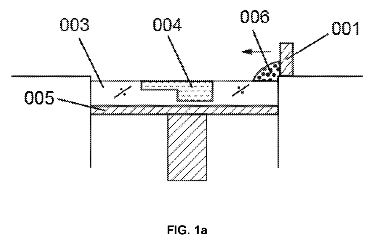
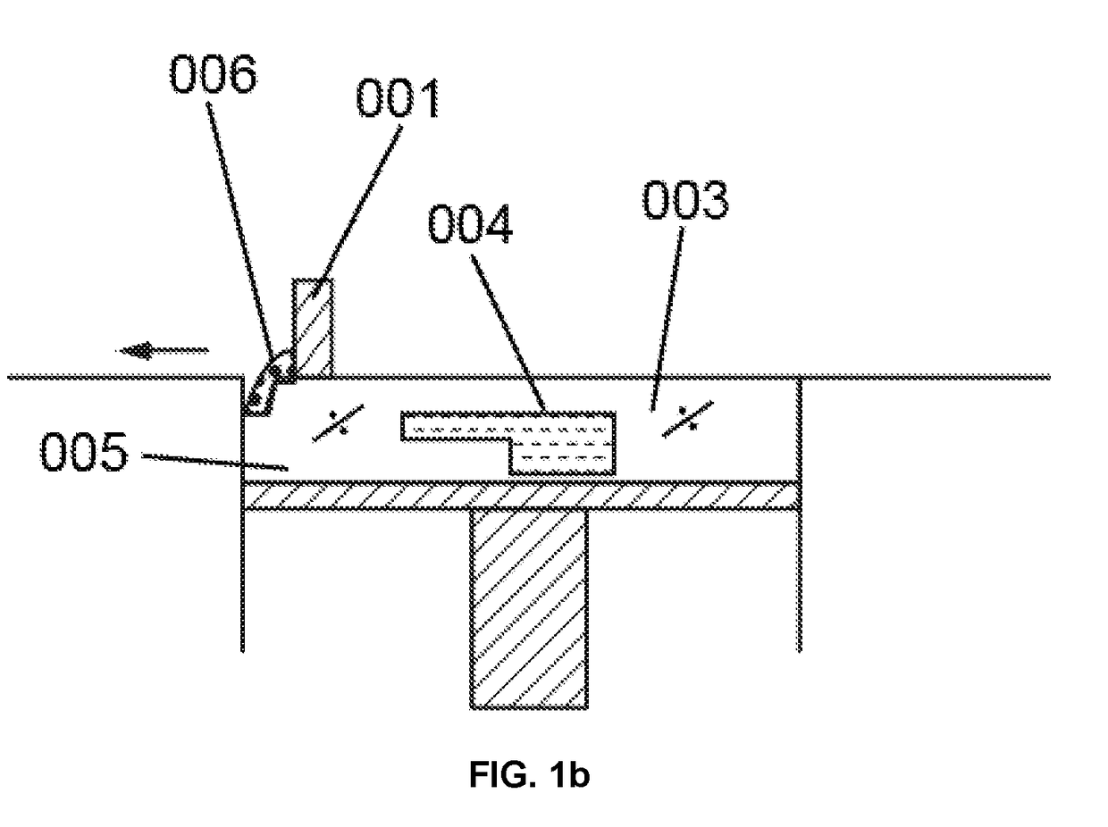
In particular, even and temperature-controlled construction material application of the powder is a challenge in prior art methods.
Due to the emission and
thermal conduction into the surrounding particulate material, the edge of the molded part cools off quicker than internal regions, which results in undesired temperature differences in the molded part, along with the above-mentioned disadvantages.
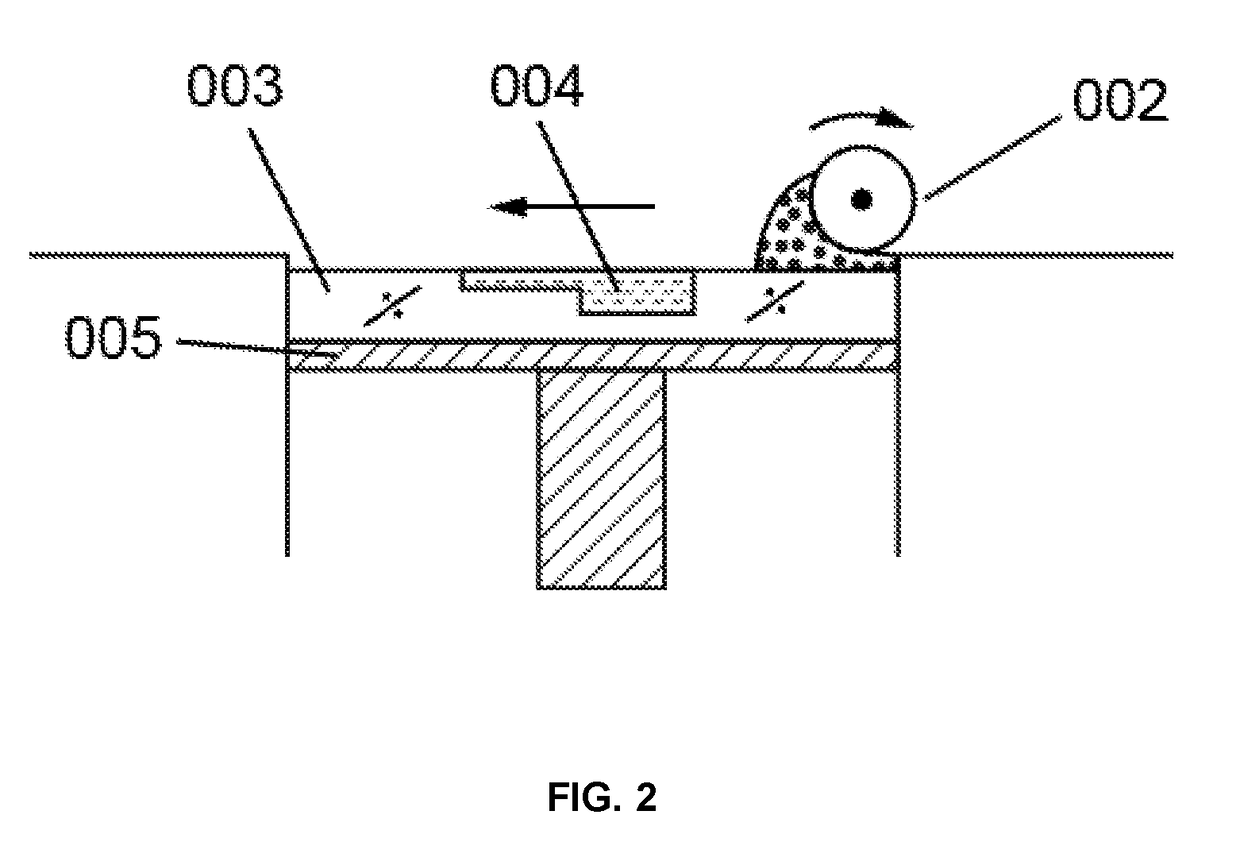
It has turned out as problematic again, in this case, that the construction space has to be kept at a high temperature so that the powder can be preheated without cooling off and the powder roll which the coater moves along in front of it does not cool down too much during material application.
Moreover, concerning the powder roll, it has proved problematic that the rotary movement results in a higher
coating speed along its
radius, which results in differences in quality among the molded articles, depending on their location.
These temperature differences, depending on the position of the molded article, result in differences in quality between the molded articles produced.

