
Fluorescent Glass For Light Emitting Diode And Manufacturing Method Thereof

a technology of fluorescent glass and light-emitting diodes, which is applied in the field of fluorescent glass, can solve the problems of affecting the lighting effect of white light-emitting diodes, high viscosity of melted glass, and flowability of melted glass, so as to achieve effective improvement of lighting efficiency of light-emitting diodes and avoid light loss in the transmission process

Inactive Publication Date: 2019-01-10
PLATINUM OPTICS TECH SUZHOU INC +1
View PDF5 Cites 0 Cited by
  • Summary
  • Abstract
  • Description
  • Claims
  • Application Information

AI Technical Summary

Benefits of technology

The present disclosure provides a fluorescent glass for a light emitting diode and its manufacturing method. The fluorescent glass is made by mixing and sintering glass powder and fluorescent powder. The glass powder has low silicon content and high boron content, which makes it easy to process. The coefficient of thermal expansion of the glass powder is similar to the coefficient of the thermal expansion of the fluorescent powder, which helps to control the temperature during the sintering process and prevents the color of the fluorescent powder from deteriorating and affecting the transparency of the fluorescent glass. This results in improved lighting efficiency of the light emitting diode. It is thus suitable for use in light emitting devices such as light emitting diodes.

Problems solved by technology

However, under the state of long time and high temperature, the silicone in the white light emitting diode easily generate yellowing and deterioration, thereby affecting the lighting effect of the white light emitting diode.
The viscosity of the melted glass is high and the flowability of the melted glass is poor, such that the subsequent process thereof is relatively difficult to operate.
The sintering temperature needs higher when the glass and the fluorescent powder are sintered, such that a stress is easily generated when sintering, and the subsequent manufacturing of the fluorescent glass is not easy.

Method used


Image

  • Fluorescent Glass For Light Emitting Diode And Manufacturing Method Thereof

Examples


Embodiment Construction

[0014]The present disclosure will now be described more fully hereinafter with reference to the accompanying drawings, in which exemplary embodiments of the invention are shown. This present disclosure may, however, be embodied in many different forms and should not be construed as limited to the embodiments set forth herein. Rather, these embodiments are provided so that this present disclosure will be thorough and complete, and will fully convey the scope of the present disclosure to those skilled in the art.

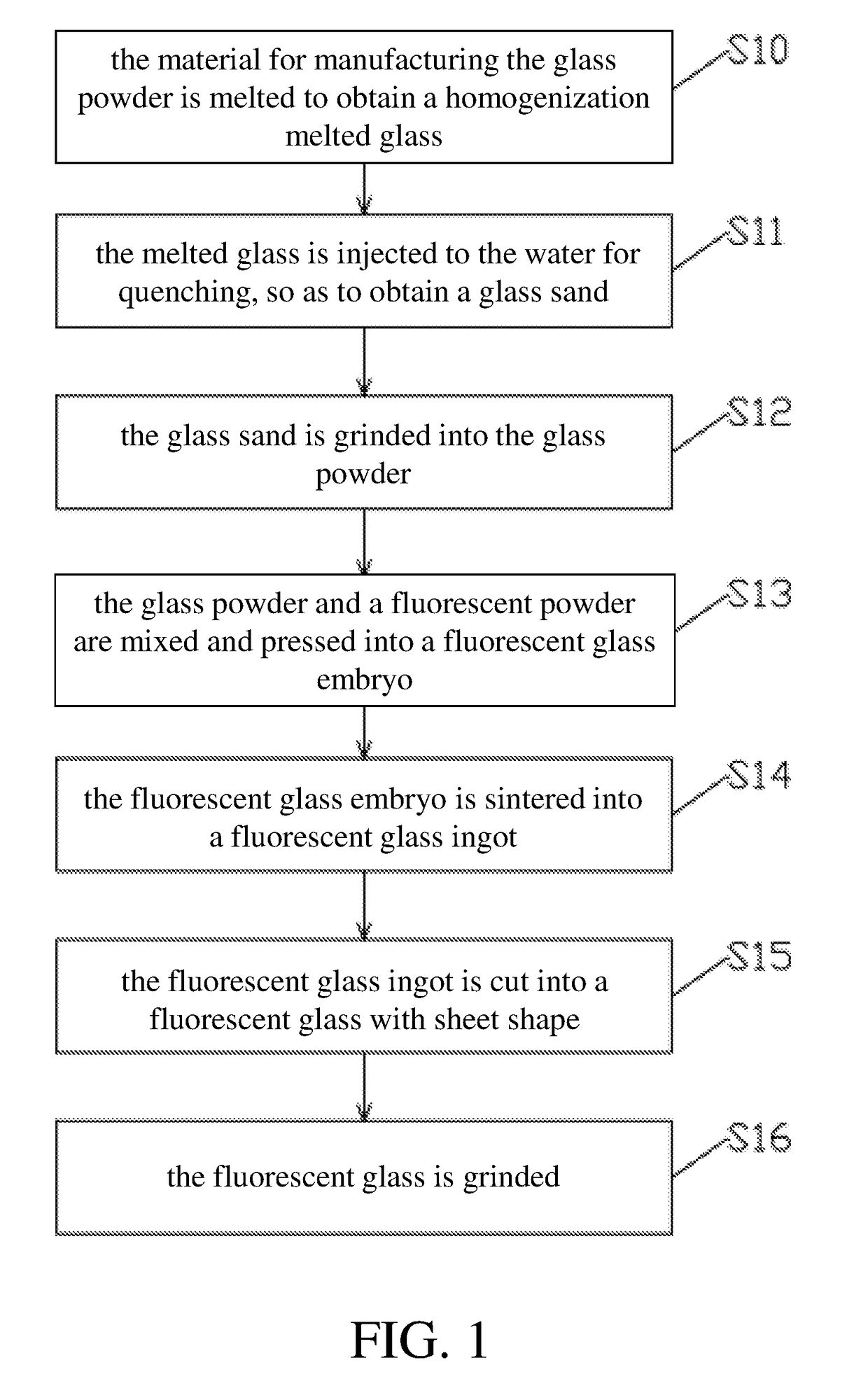
[0015]Firstly, the present disclosure provides a fluorescent glass for a light emitting diode and a manufacturing method therefore, the material of fluorescent glass for the light emitting diode includes a glass powder and a fluorescent powder, the glass powder and a fluorescent powder are mixed and pressed into a fluorescent glass embryo, and the fluorescent glass embryo is sintered, so as to form the fluorescent glass for the light emitting diode. As mentioned above, in the ...


PUM

PropertyMeasurementUnit
Temperatureaaaaaaaaaa

Abstract

The present disclosure is related to a fluorescent glass for a light emitting diode and a manufacturing method thereof. The fluorescent glass for the light emitting diode includes a glass powder and a fluorescent powder, wherein the glass powder and the fluorescent powder are mixed to form a fluorescent glass, the material for manufacturing the glass powder comprises silicon dioxide with 20 wt % to 37 wt %, diboron trioxide with 31 wt %-47 wt % and calcium oxide with 16 wt %˜35 wt %, and the material of the fluorescent powder is selected from one of Ce-YAG, LuAG, silicate, and nitrides / oxynitrides fluorescent powder. The fluorescent glass of the present disclosure is formed by mixing and sintering the glass powder and the fluorescent powder and has low sintering temperature, so as to avoid the deterioration of color of the fluorescent powder due to high temperature. Therefore, the fluorescent glass of the present disclosure has good transparency, and the light emitting diode applying this fluorescent glass has good lighting efficiency.

Description

CROSS REFERENCE TO RELATED APPLICATION[0001]This application claims the priority benefit of China Patent Application Serial Number 201710536022.3, filed on Jul. 4, 2017, the full disclosure of which is incorporated herein by reference.BACKGROUNDTechnical Field[0002]The present disclosure generally relates to a fluorescent glass and, more particularly, to a fluorescent glass for a light emitting diode and a manufacturing method thereof.Related Art[0003]Currently, the white light emitting diode is formed by mixing and coating the fluorescent powder and the polymer silicone on a blue light chip. The blue light chip lights to excite the fluorescent powder, so as to generate yellow light, and the yellow light and the blue light is mixed to form the white light. However, under the state of long time and high temperature, the silicone in the white light emitting diode easily generate yellowing and deterioration, thereby affecting the lighting effect of the white light emitting diode. Curre...

Claims


Application Information

Patent Timeline
IPC IPC(8): C03C4/12H01L33/50C09K11/02C03C14/00C03C3/064C03B19/06
CPCC03C4/12H01L33/502H01L33/507H01L2933/0041C03C14/004C03C3/064C03B19/06C09K11/025C03C3/068C03C3/066H01L33/501Y02P40/57
Inventor LU, CHUN-YUANLIAO, YI-YAOLIN, CHUN-TENG
Owner PLATINUM OPTICS TECH SUZHOU INC
Learn More