Immersive Optical Projection System

Active Publication Date: 2019-01-24
MAYNARD RONALD S
View PDF0 Cites 7 Cited by
  • Summary
  • Abstract
  • Description
  • Claims
  • Application Information

AI Technical Summary

Benefits of technology

The invention is an improved system for creating virtual, augmented, or mixed reality experiences. It uses an optical system to stimulate the retina, resulting in stabilized images that align with the body's visual system. The system also creates a realistic sense of depth and produces an immersive experience. It includes a large color space and a full field of view, and may include immersive audio. The system is also cost-effective, versatile, and can deliver higher resolution to the central field of vision.

Problems solved by technology

Most are limited by frame rate, brightness, and the production of a truly divergent ray field that a near object would produce.
And of course, they are all subject to the flat field, limited resolution, limited dynamic range and limited angular extent of the distant screen.
Using a combination of scanners and optical elements, a virtual image can be produced at any apparent depth, but is usually limited by a narrow angle of view.
Most provide a modest field of view, and are limited in delivering continuous, truly divergent fields that are ubiquitous in the real world.
These head mounted systems often have a bulky form factor, and are hard wired to a power source, a data processing unit, or a personal computer.
AR systems also suffer from limited control of the lighting environment.
A problem occurs when attempting to overlay a dark simulated object onto a bright real background.
When a beachgoer gazes through an AR headset and looks to the bright horizon, it is not possible to observe the overlay of a black containership.
Nor is it possible to accurately control shadows.
In general, current devices are hampered by their inability to sufficiently synchronize precise head motions with stabilized imagery, producing a disturbing visual lag.
This can be attributed, in part, to sensor deadband issues, software computation delays, digital content protection, and LCD switching speeds.
Further, stereopsis cannot be fully achieved unless a true 3D image is presented to the eyes.
In addition, virtual systems that do not synchronize binocular vision with natural depth of field cues create a vergence-accommodation conflict.
All of these sensory conflicts can negatively affect the human vestibular and ocular systems resulting in disorientation and what is termed “virtual reality sickness”.
Finally, systems that lack eye tracking capabilities are incapable of dynamic data allocation that can efficiently address the greater needs of central vision.

Method used


Image

  • Immersive Optical Projection System
  • Immersive Optical Projection System
  • Immersive Optical Projection System

Examples


Embodiment Construction

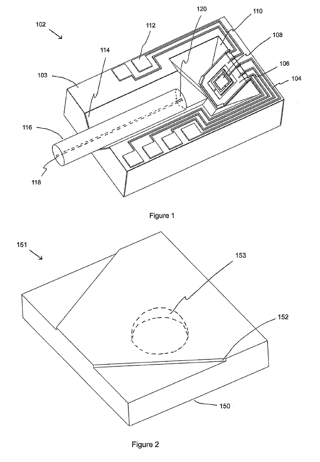
[0045]FIG. 1 shows an example of a monolithically micromachined beam steering device 102. Its design and function is the subject of patents U.S. Pat. No. 5,872,880, U.S. Pat. No. 6,086,776, U.S. Pat. No. 6,127,926, and U.S. Pat. No. 7,201,824 B2. In one embodiment, light is first introduced into the core of optical element 116 at point 118 and is emitted at point 120. The slightly divergent beam then travels a short distance through free space and strikes the surface of double gimbaled micromirror 108. In another embodiment, an optical beam modifier, such as a ball lens, a GRIN lens, or any other optical element may be introduced after point 120 to further alter the beam before striking double gimbaled micromirror 108. In another embodiment, an optical beam modifier may be introduced after striking micromirror 108. Two additional examples of beam modifiers include an electrostatic comb driven, variable focus lens that dynamically controls beam divergence and has an optical axis that...


PUM


Abstract

An improved virtual reality system comprising an immersive sound system, sensors, a power source, communications, data processing, and an optical system that delivers photoreceptor density resolution, wide angle, high contrast, binocular vision, continuous depth of field images, is integrated for a fully immersive experience. In one embodiment, an optical system comprises a miniaturized array of projectors geometrically arranged to cover the photoreceptive areas of the retina. The projectors provide full spectrum, amplitude modulated, and controllably divergent beams of light that can be steered with one or more degrees of freedom. These beams are subsequently reflected off a compound curved reflector, through additional optics, and along reversible light paths to form images on the retina. Segmented projector arrays greatly improve dynamic performance. In another embodiment, an adaptive optics reflector is comprised of an array of fixed, or independently controllable optical elements, that can alter reflected beam properties such that a virtual object may appear to be nearer to, or further from the viewer. In yet another embodiment, a direct projection, two dimensional array of micro projectors are positioned to deliver a fully immersive image directly into the eye. Binocular embodiments can elicit an accurate vergence-accommodation reflex, produce stabilized images that are closely synchronized with the vestibulo-ocular reflex, and create lifelike binocular disparities that produce a faithful sense of stereopsis, an important factor for the avoidance of virtual reality motion sickness.

Description

CROSS-REFERENCE TO RELATED APPLICATIONS[0001]This patent application claims the benefit of U.S. provisional patent application Ser. No. 62 / 399,530, filed on the 26th of Sep., 2016 by the present inventor.TECHNICAL FIELD[0002]The present disclosure relates to a virtual reality system that in one case, provides a photoreceptor density limiting, wide angle, full spectrum, binocular vision, real optical depth of field, imaging system in a head mounted form factor.BACKGROUND ART[0003]Many devices have been created to deliver optical information to the human eye. Visual information can take the form of high definition video, computer generated content, two and three dimensional content, text, etc. The visual component of a virtual reality system delivers synthetic content directly to the eye, whereas augmented reality systems blend generated content with real world views.[0004]In nature, every illuminated particle reflects or emits rays of light in every direction and in a multitude of wa...

Claims


Application Information

Patent Timeline
IPC IPC(8): G03B21/28G02B27/00G06F3/01G02B26/12H04R1/02G02B27/01
CPCG03B21/28G02B27/0037G06F3/013G02B26/12H04R1/025G02B27/0172G02B27/0176G02B2027/0178G02B1/002G02B5/12G02B26/0825G02B26/0841H04N9/3129H04N9/3147G02B2027/0187
Inventor MAYNARD, RONALD S.
Owner MAYNARD RONALD S
Why Eureka
Try Eureka