Cutting fluid intelligent recycling device

a recycling device and cutting fluid technology, applied in the direction of filtration separation, manufacturing tools, separation processes, etc., can solve the problems of affecting the cutting fluid, so as to effectively block the breeding of bacteria, eliminate the undesirable odor spreading, and improve the filter effect

Active Publication Date: 2019-03-07
DONGGUAN XUNMEI ENVIRONMENTAL PROTECTION TECH INC
View PDF6 Cites 17 Cited by
  • Summary
  • Abstract
  • Description
  • Claims
  • Application Information

AI Technical Summary

Benefits of technology

[0011]Based on this, it is necessary to provide a cutting fluid intelligent recycling device specific to the deficiencies of the existing technology, which can effectively remove the cuttings, iron powder, floating oil stain and cutting fluid residue in the dirty fluid of cutting fluid to ensure a very good filtering effect and recycle the dirty fluid after treatment, having effectively reduce the emission quantity of wastewater and maintained the stability of the ecological environment.
[0022]The cutting fluid intelligent recycling device of the present invention can effectively remove the cuttings, iron powder, floating oil stain, cenobium, floccule and impurities in the cutting fluid dirty fluid through the first-level filtering device, second-level filtering device and third-level filtering device to ensure a very good filtering effect and also sterilize and deodorize the cutting fluid dirty fluid so that the cutting fluid flowing into the clean liquid tank is basically aseptic and odorless with its floating oil stain content lower than 0.5% and impurity particle less than 0.01 mm to prolong the service life of cutting fluid and effectively reduce the cutting fluid use cost. Secondly, it can effectively block the bacteria breeding and eliminate the undesirable odor spreading to protect the human health. Moreover, it can prolong the service life of the tools using the cutting fluid, improve the part processing quality and reduce the time of dirty fluid cleaning by the working personnel, thus reducing the device maintenance cost, increasing the work efficiency and also improving the workshop air quality and protecting the ecological environment ultimately.

Problems solved by technology

However, the problems like deterioration, becoming stinky and dirty fluid treatment and emission would all be encountered during the normal application of the cutting fluid.
This is the basic reason causing the cutting fluid to become stinky and deteriorate.
The bacteria bred mainly include the two categories of aerobic bacteria and anaerobic bacteria, whichever can bring great harm to the cutting fluid.
1. The anaerobic bacteria can reduce sulfate, thiosulfate, sulfite, etc. to release thiol and hydrogen sulfide gases and produce foul smell, thus destroying the ecological environment and affecting the human health.
2. The metabolism of bacteria would produce some acidic substances to cause corrosion to the machine tool and workpiece and destroy the stability of emulsion, thus greatly reducing the lubricating performance of cutting fluid.
3. The bacteria destroy the oiliness additive and extreme pressure additive in the cutting fluid, which causes the friction force increase and calorific value increase during processing and results in poorly finished surface and tool service life shortening ultimately.
To sum up, the deterioration of cutting fluid would not only bring many adverse consequences to the metal cutting processing, but also result in the cutting fluid wasting and ecological environment destruction.
Moreover, under the adverse influence of the deteriorated cutting fluid, the machine tool device maintenance cost and the time of dirty fluid cleaning by the working personnel would be increased, affecting the work efficiency.

Method used


Image

  • Cutting fluid intelligent recycling device
  • Cutting fluid intelligent recycling device
  • Cutting fluid intelligent recycling device

Examples


Embodiment Construction

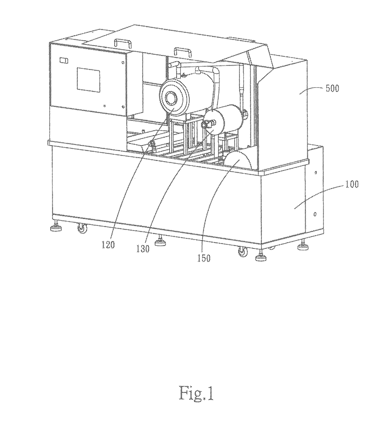
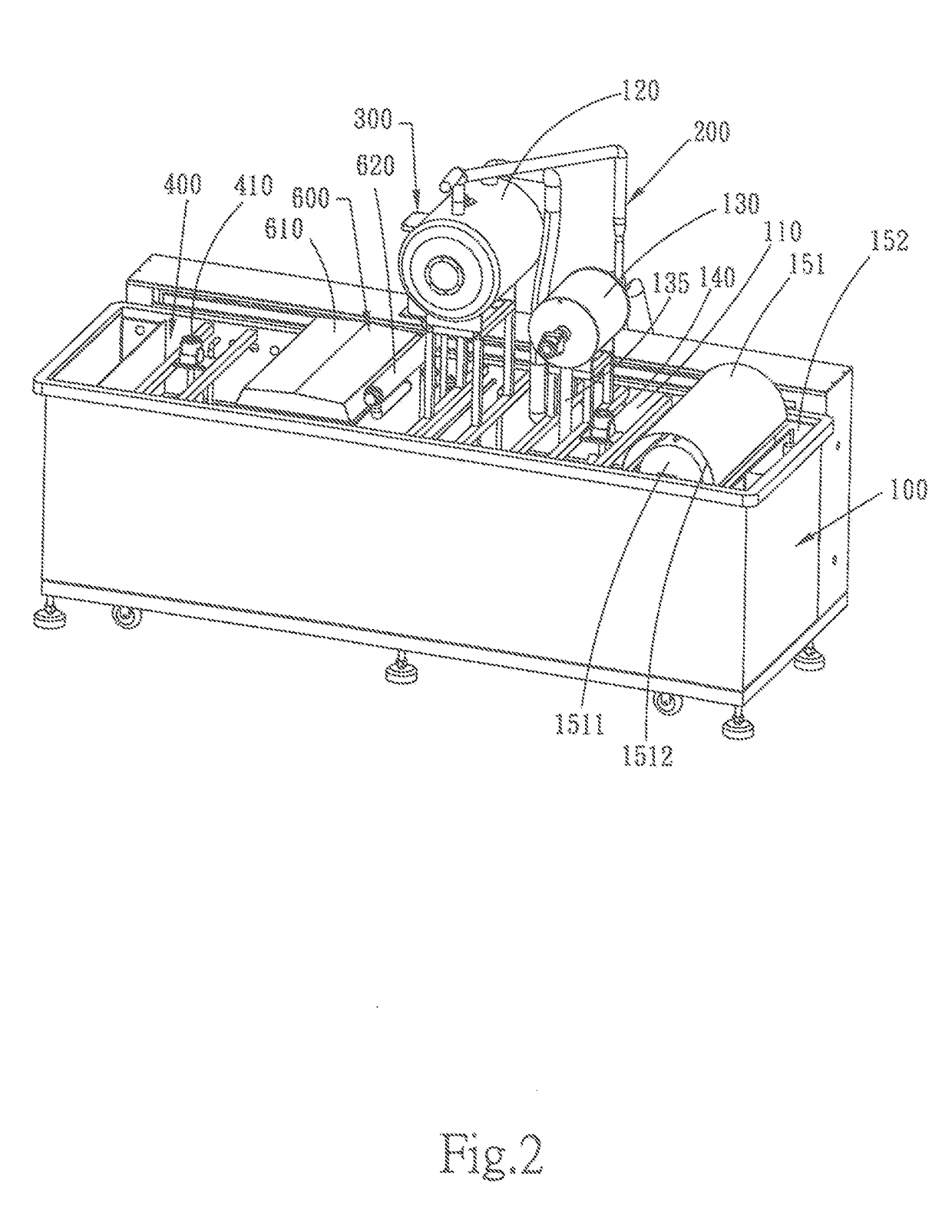
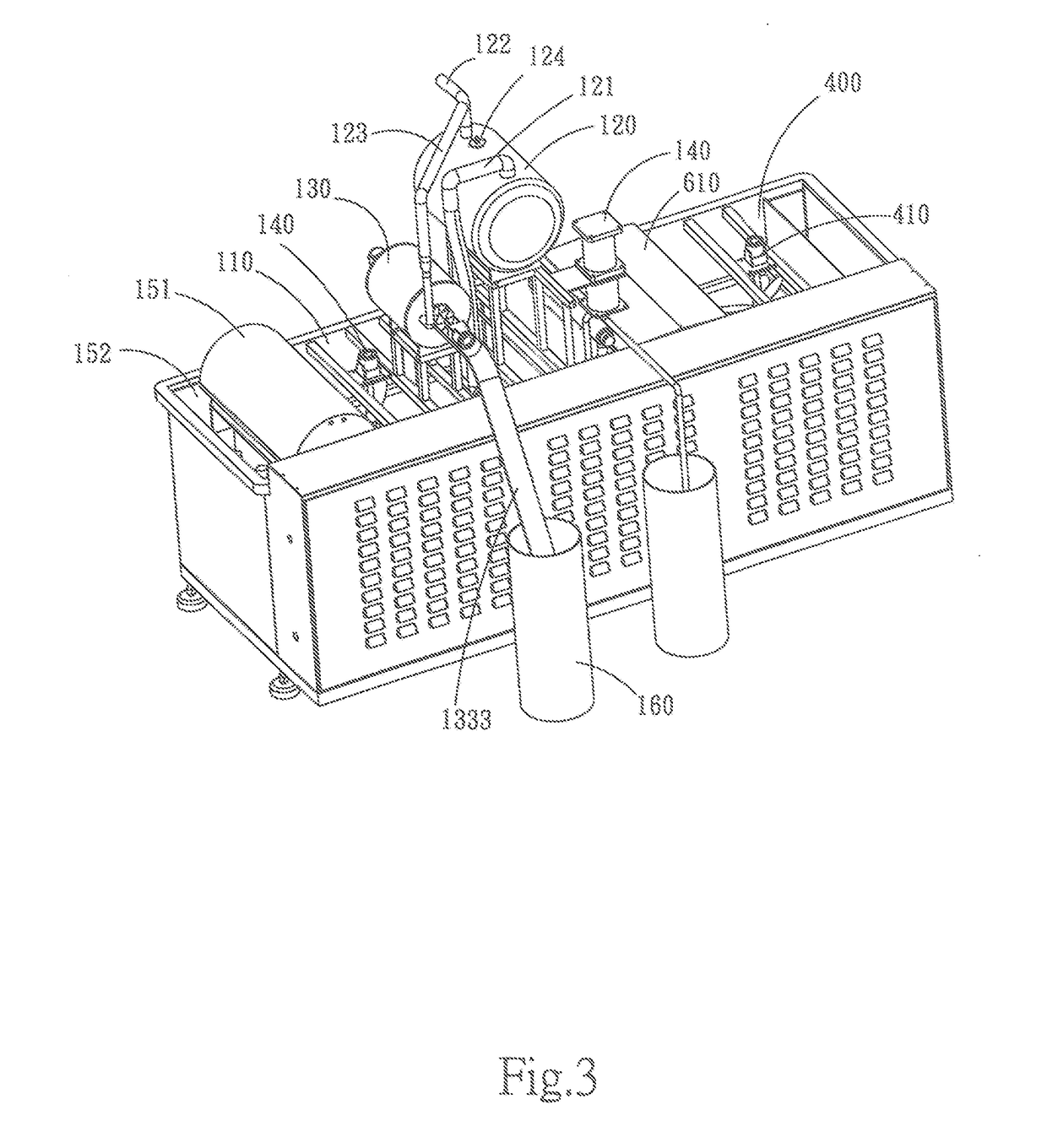
[0033]The invention will be further described in details hereinafter.

[0034]Referring to FIGS. 1 to 5, a cutting fluid intelligent recycling device comprises a frame 100 and a first-level filtering device 200, second-level filtering device 300, third-level filtering device 600 and clean liquid tank 400 installed on the frame 100. The cover body 500 is fixed and provided on top of the frame 100 used to cover the first-level filtering device 200, second-level filtering device 300 and clean liquid tank 400 to avoid the interference to the first-level filtering device 200, second-level filtering device 300, third-level filtering device 600 and clean liquid tank 400 by the external environment and increase the filtering effect of the cutting dirty fluid.

[0035]The first-level filtering device 200 is provided at one side of the frame; the first-level filtering device 200 is provide with the dirty fluid tank 110 used for containing liquid; the dirty fluid tank 110 is installed and provided w...


PUM

PropertyMeasurementUnit
vacuumaaaaaaaaaa
liquid levelaaaaaaaaaa
cutting temperatureaaaaaaaaaa

Abstract

A cutting fluid intelligent recycling device, comprises a frame, a first-level filtering device, second-level filtering device, and clean liquid tank installed on the frame; the first-level filtering device being provided with a dirty fluid tank used for containing liquid, the dirty fluid tank having a dirty fluid suction device and dirty fluid treatment device; through the first-level and second-level filtering devices, the cutting fluid intelligent recycling device can remove the cuttings, iron powder, floating oil stain, cenobium, floccule and impurities in the cutting dirty fluid and also sterilize and deodorize the cutting fluid coolant to prolong its service life.

Description

BACKGROUND OF INVENTION1. Field of the Invention[0001]The present invention relates to a field of a cutting fluid intelligent recycling device.2. Description of Related Art[0002]With the overall technology development of the mechanical industry, the machine tool cutting speed is faster, the cutting load is bigger, the cutting temperature is higher and new processes constantly emerge to adapt to the new material processing; and all these need some new-type high-performance cutting fluid to satisfy the processing requirements. Therefore, the cutting fluid development has become a trend.[0003]The cutting fluid is a kind of industrial liquid used for cooling and lubricating the tools and workpieces during the metal cutting and grinding process. The cutting fluid is compounded of multiple super-strong function additives scientifically and characteristic of good cooling performance, lubricating performance, anti-rust resistance, degreasing and cleaning function and anticorrosive function ...

Claims


Application Information

Patent Timeline
Patent Type & Authority Applications(United States)
IPC IPC(8): B03C1/033B03C1/28B03C1/30B23Q11/00
CPCB03C1/0332B03C1/286B03C1/30B23Q11/005B01D33/11B03C2201/18B01D33/50B01D35/06B23Q11/1069B03C2201/20
Inventor FENG, JIAN
Owner DONGGUAN XUNMEI ENVIRONMENTAL PROTECTION TECH INC
Why Eureka
Try Eureka