
Below freezing start-up method for fuel cell system

a fuel cell and system technology, applied in the field of improved methods for starting up a fuel cell system, can solve the problems of ice formation, ice formation in the electrochemically active areas of the fuel cell, and ice formation of cours

Active Publication Date: 2019-07-04
CELLCENTRIC GMBH & CO KG +2
View PDF0 Cites 3 Cited by
  • Summary
  • Abstract
  • Description
  • Claims
  • Application Information

AI Technical Summary

Benefits of technology

The patent describes a method for controlling the maximum current density and voltage of a fuel cell system to prevent carbon corrosion and other damage. The method involves monitoring the individual voltage of each fuel cell in the stack and reducing the current if any voltage drops below a certain level. This prevents blockages in the flow fields and ensures the fuel cell operates efficiently and safely. The technical effect of this method is the improved performance and durability of fuel cell systems.

Problems solved by technology

This has posed a significant challenge both because of the relatively low rate capability of cells at such temperatures and also because of problems associated with water management in the cells when operating below 0° C. A certain amount of water is required for proper fuel cell operation (e.g. hydration of the membrane electrolyte) and water is also generated as a result of providing electrical power.
However, ice of course forms where liquid water is present at such temperatures.
The presence of ice can be problematic depending on how much there is and its location when stored or when starting up.
The formation of ice in the electrochemically active areas of the fuel cells can be particularly problematic during startup from below freezing temperatures.
The now inadequate supply of fuel in that cell or cells can result in a condition known as fuel starvation.
The latter reactions can result in irreversible damage.

Method used


Image

  • Below freezing start-up method for fuel cell system
  • Below freezing start-up method for fuel cell system
  • Below freezing start-up method for fuel cell system

Examples


examples

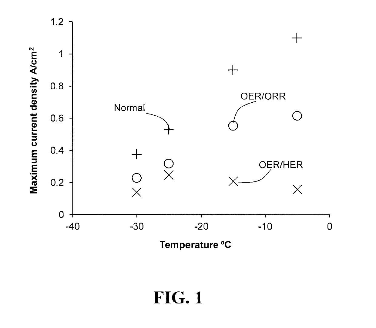
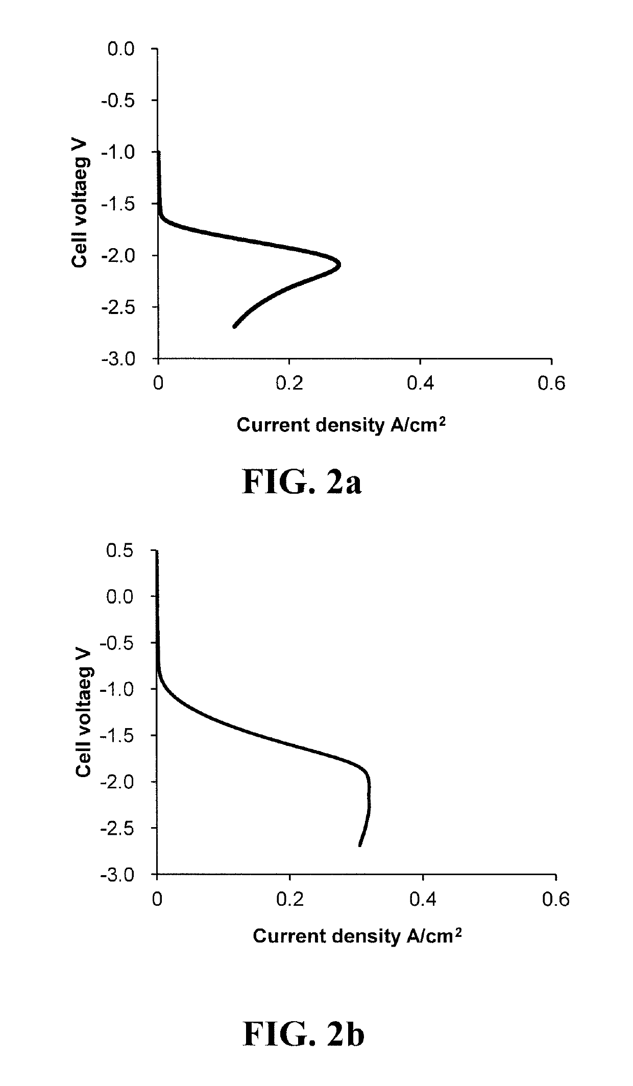
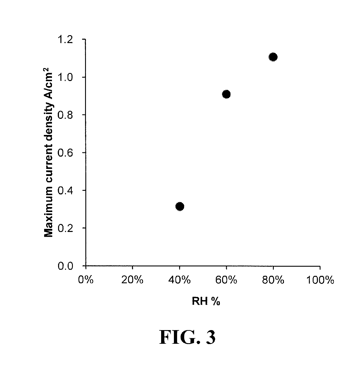
[0053]An experimental fuel cell was prepared using conventional components and construction techniques. Then, the fuel cell's maximum current density was determined under various conditions as a function of temperature and of relative humidity.

[0054]The experimental fuel cell comprised a catalyst coated membrane (CCM) sandwiched between two carbon fibre gas diffusion layers (GDLs). The membrane electrolyte in the CCM was a conventional Nafion® perfluorosulfonic ionomer membrane. The anode comprised both a HOR and an OER catalyst, namely carbon black supported platinum and iridium oxide powder respectively. The cathode comprised an ORR catalyst which was also carbon black supported platinum. Flow field plates were applied to each of the GDLs and the assembly was completed in a conventional manner. The cell was then conditioned by operating at a constant current density, with hydrogen and air as the supplied reactants for several hours to obtain a stable steady-state performance. Maxi...


PUM


Abstract

Methods are disclosed for starting up a fuel cell system from starting temperatures below 0° C. The methods apply to systems comprising a solid polymer electrolyte fuel cell stack whose cathodes comprise an oxygen reduction reaction (ORR) catalyst and whose anodes comprise both a hydrogen oxidation reaction (HOR) catalyst and an oxidation evolution reaction (OER) catalyst. In the methods, from the beginning of starting up until the fuel cell temperature reaches 0° C., the fuel cell stack current is kept sufficiently low such that the current density drawn does not exceed the stack's capability for the oxidation evolution and the oxygen reduction reactions to occur at the anode and cathode respectively (i.e. current density drawn is less than the stack's maximum OER / ORR current density).

Description

BACKGROUNDField of the Invention[0001]This invention relates to improved methods for starting up a fuel cell system at temperatures below freezing. In particular, it relates to methods for starting up an automotive fuel cell system comprising a solid polymer electrolyte fuel cell stack.Description of the Related Art[0002]Fuel cells such as solid polymer electrolyte fuel cells electrochemically convert reactants, namely fuel (such as hydrogen) and oxidant (such as oxygen or air), to generate electric power. Solid polymer electrolyte fuel cells generally employ a proton conducting, solid polymer membrane electrolyte between cathode and anode electrodes. A structure comprising a solid polymer membrane electrolyte sandwiched between these two electrodes is known as a membrane electrode assembly (MEA). MEAs in which the electrodes have been coated onto the membrane electrolyte to form a unitary structure are commercially available and are known as a catalyst coated membrane (CCM).[0003]C...

Claims


Application Information

Patent Timeline
IPC IPC(8): H01M8/04223H01M8/04858H01M8/0432H01M8/10H01M8/04537
CPCH01M8/04268H01M8/0491H01M8/0432H01M8/10H01M8/04559H01M8/04649H01M2008/1095H01M2250/20H01M8/186Y02E60/50Y02T90/40
Inventor PROCTER, MICHAELFUKUYAMA, YOSUKEFELLOWS, RICHARDSHIOMI, TAKESHIIWAN, LAURA
Owner CELLCENTRIC GMBH & CO KG
Learn More