Method for rapidly forming a part using combination of arc deposition and laser shock forging and device implementing same

Active Publication Date: 2019-11-07
GUANGDONG UNIV OF TECH
View PDF4 Cites 11 Cited by
  • Summary
  • Abstract
  • Description
  • Claims
  • Application Information

AI Technical Summary

Benefits of technology

[0020]In operation, the arc welding device performs an arc deposition on the workbench to form a melting deposition layer, the temperature of the arc deposition region is in the range of plastic deformation temperature. The controller controls the laser device to perform synchronous shock forging on the arc deposition region of the melting deposition layer, which not only ensures the rapid forming of the parts, improves the manufacturing efficiency, but also ensures the forming quality of the parts, refines the grains of the melting deposition layer, eliminates the internal defects such as the pores of the melting deposition layer as well as the thermal stress and the residual stress, and effectively controls the macroscopic deformation and cracking problems significantly improves the internal quality and comprehensive mechanical properties of the part. The problem of flowing, shedding and collapsing of fused processing materials is solved as the result of using computer to control the multi-degree-of-freedom spatial motion platform.
[0021]2. The computer of the present invention obtains the parameters of the melting deposition layer within the forging temperature interval according to the obtained temperature, thickness and morphology data of the melting deposition layer, controls the pulse laser to work, and adjusts the output energy, pulse wid

Problems solved by technology

In order to solve the problem that the internal defects generated during the forming process of the parts in the existing rapid manufacturing such as pores, incomplete fusion, cracks and shrinkage porosi

Method used


Image

  • Method for rapidly forming a part using combination of arc deposition and laser shock forging and device implementing same
  • Method for rapidly forming a part using combination of arc deposition and laser shock forging and device implementing same
  • Method for rapidly forming a part using combination of arc deposition and laser shock forging and device implementing same

Examples


embodiments

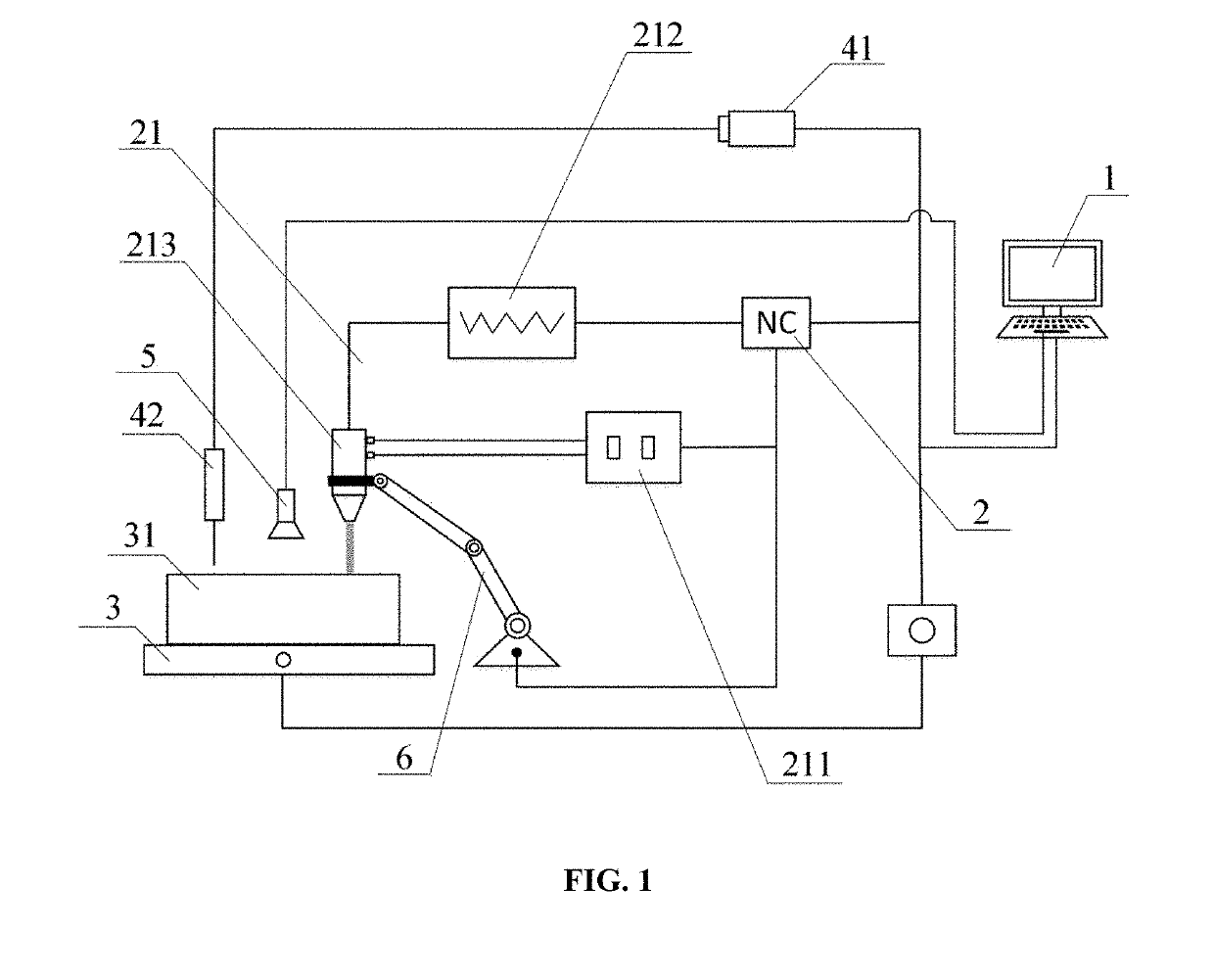
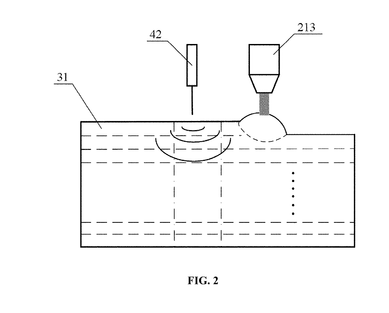
[0028]According to FIGS. 1 and 2, the embodiment relates to a method for rapidly forming a part using combination of arc deposition and laser shock forging, including the following steps.

[0029]1) A 3D model of the part is drawn and imported into a simulation system of a computer 1. A preforming part model is divided into one or more simple forming units by the simulation system. A forming order of the forming units is determined. The forming units are laminated and sliced in a stack direction. The data is processed according to the laminated slices to generate a numerical control code for processing slices respectively. As shown in FIG. 1, the 3D model of the part is drawn by using the simulation software in the computer 1, or using other 3D drawing software (such as SolidWorks, UG, etc.) to draw the 3D model and imported into the simulation software. The preforming part model is divided into one or more simple forming units. The forming order of the forming units is determined. The...


PUM


Abstract

A method for rapidly forming a part using combination of arc deposition and laser shock forging, including: 1) dividing a preforming part model into one or more simple forming units by the simulation system and determining a forming order of the forming unit; 2) controlling, by the numerical control device, an arc welding device to perform a melting deposition forming of a processing material layer by layer on a processing substrate of a motion platform to form a melting deposition layer; 3) controlling, by the computer, a movement of the motion platform to keep a fusion zone always in a horizontal state, at the same time, a pulse laser beam of a laser device to perform a synchronous shock forging on an arc deposition region at a plastic deformation temperature. A device for implementing the method.

Description

CROSS-REFERENCE TO RELATED APPLICATIONS[0001]This application is a continuation of International Application No. PCT / CN2017 / 094100, filed on Jul. 24, 2017, which claims priority from Chinese Patent Application No. 201710500880.2, filed on Jun. 27, 2017, both of which are hereby incorporated by reference in their entireties.TECHNICAL FIELD[0002]The present invention relates to a method and a device for manufacturing a part and a mold by forging, in particular to a method for rapidly forming a part using combination of arc deposition and laser shock forging and a device implementing same.BACKGROUND OF THE INVENTION[0003]With the rapid development of modern industrial technology, there is an increasing requirement of the manufacture of structures and certain key components and their service performance, such as low cost, short process and non-polluting manufacture, as well as excellent comprehensive physical and mechanical properties, etc. Direct rapid forming manufacturing technology ...

Claims


Application Information

Patent Timeline
IPC IPC(8): B23K9/04B33Y10/00B33Y30/00B33Y40/00B33Y50/00B33Y70/00B23K9/095B23K26/356B23K26/348
CPCB23K9/0953B23K26/348B23K26/356B33Y50/00B33Y30/00B23K9/042B33Y10/00B33Y40/00B33Y70/00B23K9/0956B22F12/43B22F10/22B22F10/25B22F12/41B22F10/38B22F10/80B33Y50/02B23K9/04C04B2235/6026C04B2235/665Y02P10/25
Inventor ZHANG, YONGKANGYANG, QINGTIANYANG, ZHIFANZHANG, ZHENGYU, QIUYUN
Owner GUANGDONG UNIV OF TECH
Why Eureka
Try Eureka