Logic drive using standard commodity programmable logic IC chips

a logic drive and programmable logic technology, applied in the direction of logic circuit coupling/interface arrangement, logic devices, logic packages, etc., can solve the problems of higher fabrication cost, lower fabrication yield, and consumption of power, and achieve the effect of reducing the manufacturing cost of the standard commodity fpga ic chip, maximum manufacturing yield, and minimum manufacturing cos

Active Publication Date: 2019-11-28
ICOMETRUE CO LTD
View PDF0 Cites 38 Cited by
  • Summary
  • Abstract
  • Description
  • Claims
  • Application Information

AI Technical Summary

Benefits of technology

[0012]Another aspect of the disclosure provides a standard commodity FPGA IC chip for use in the standard commodity logic drive. The standard commodity FPGA IC chip is designed, implemented and fabricated using an advanced semiconductor technology node or generation, for example more advanced than or equal to, or below or equal to 20 nm or 10 nm, for example using the technology node of 16 nm, 14 nm, 12 nm, 10 nm, 7 nm, 5 nm or 3 nm. The manufacturing cost of the standard commodity FPGA IC chip can be reduced due to: (i) optimized chip size: Since the FPGA functions can be partitioned into several FPGA IC chips packaged in the logic drive, the FPGA chip size can be optimized for maximum manufacturing yield, therefore resulting in a minimum manufacturing cost. The standard commodity FPGA IC chip may have an area between 400 mm2 and 9 mm2, 144 mm2 and 16 mm2, 75 mm2 and 16 mm2, or 50 mm2 and 16 mm2; (ii) regular circuit arrays: All or most control circuits, Input / Output (I / O) circuits or units (for example, the off-logic-drive I / O circuits, i.e., large I / O circuits, communicating with circuits or components external or outside of the logic drive), and / or hard macros (for example, DSP slices, microcontroller macros, fixed-wired adders, and / or fixed-wired multipliers) are outside of, or not included in, the standard commodity FPGA IC chip, but are included in another dedicated control chip, dedicated I / O chip, dedicated control and I / O chip, ASIC chip, CPU chip, and / or DSP chip, packaged in the same logic drive. The standard commodity FPGA IC chip may only communicate directly with other chips in or of the logic drive only; its I / O circuits may require only small I / O drivers or receivers, and small or none Electrostatic Discharge (ESD) devices. The driving capability, loading capability, output capacitance, or input capacitance of I / O drivers or receivers, or I / O circuits may be between 0.1 pF and 2 pF or 0.1 pF and 1 pF. The size of the ESD device may be between 0.05 pF and 2 pF or 0.05 pF and 1 pF. For example, a bi-directional (or tri-state) I / O pad or circuit may comprise an ESD circuit, a receiver, and a driver, and has an input capacitance, output capacitance or loading capacitance between 0.1 pF and 2 pF or 0.1 pF and 1 pF. A lower supply voltage may be used for the standard commodity FPGA chips, and the supply voltage may be smaller or equal to 1.5 V, 1.0 V, 0.7 V or 0.5 V. The standard commodity FPGA IC chip with low power consumption and high performance is due to small I / O circuits therein, and lower power supply voltage. None or minimal area of the standard commodity FPGA IC chip is used for the control circuits, I / O circuits or hard macros, for example, less than 15%, 10%, 5%, 2% or 1% area (not counting the seal ring and the scribe line (kerf or die saw area) of the chip; that means, only including area up to the inner boundary of the seal ring) is used for the control circuits, I / O circuits or hard macros; or, none or minimal transistors of the standard commodity FPGA IC chip are used for the control circuits, I / O circuits or hard macros, for example, less than 15%, 10%, 5%, 2% or 1% of the total number of transistors are used for the control circuits, I / O circuits or hard macros. All or most area of the standard commodity FPGA IC chip is used for repetitive circuit arrays, wherein each of the repetitive circuit arrays comprises a plurality of repetitive circuit units each comprising: (i) a logic cell comprising Look-Up-Tables (LUTs) and multiplexers, and / or (ii) SRAM cells for programmable interconnection. The logic cells may be programmed or configured as functions of, for example, DSP, microcontroller, adders, and / or multipliers. For example, greater than 85%, 90%, 95% or 99% area (not counting the seal ring and the scribe line (kerf or die saw area) of the chip; that means, only including area up to the inner boundary of the seal ring) is used for repetitive circuit arrays comprising logic cells and / or SRAM cells for programmable interconnection; or, all or most transistors of the standard commodity FPGA IC chip are used for repetitive circuit arrays comprising logic cells and / or SRAM cells for programmable interconnection. A manufacture process can be tuned or optimized for the regular repetitive circuit arrays with a high manufacture yield and therefore reducing the manufacture costs.
[0013]Another aspect of the disclosure provides a method of circuit repair for a standard commodity FPGA IC chip for use in the standard commodity logic drive, wherein the method of the circuit repair increases the yield of the FPGA IC chip, therefore reducing the manufacture cost of the FPGA IC chip.
[0014]Another aspect of the disclosure provides the standard commodity logic drive in a multi-chip package comprising the standard commodity plural FPGA IC chips, for use in different algorithms, architectures and / or applications requiring logic, computing and / or processing functions by field programming, wherein the standard commodity plural FPGA IC chips, each is in a bare-die format or in a single-chip or multi-chip package. Each of standard commodity plural FPGA IC chips may have standard common features, counts or specifications: (1) a regular repetitive logic arrays with the number of logic arrays or sections equal to or greater than 2, 4, 8, 10 or 16, wherein the regular repetitive logic array includes logic blocks or elements with the count equal to or greater than 128K, 512K, 1M, 4M, 8M, 16M, 32M or 80M and / or (2) a regular memory array with the number of memory banks equal to or greater than 2, 4, 8, 10 or 16, wherein the regular memory array includes memory cells with the bit count equal to or greater than 1M, 10M, 50M, 100M, 200M or 500M bits; (2) the number of inputs to each of the logic blocks or operators: the number of inputs to each of the logic block or operator may be greater or equal to 4, 8, 16, 32, 64, 128, or 256; (3) the power supply voltage: the voltage may be between 0.1V and 1.5V, 0.1V and 1.0V, 0.1V and 0.7V, or 0.1V and 0.5V; (4) the I / O pads, in terms of layout, location, number and function. Since the FPGA chips are standard commodity IC chips, the number of FPGA chip designs or products for each technology node is reduced to a small number, therefore, the expensive photo masks or mask sets for fabricating the FPGA chips using advanced semiconductor nodes or generations are reduced to a few mask sets. For example, reduced down to between 3 and 20 mask sets, 3 and 10 mask sets, 3 and 5 mask sets, or 1 and 3 mask sets for a specific technology node or generation. The NRE and production expenses are therefore greatly reduced. With the few designs and products, the manufacturing processes may be tuned or optimized for the few chip designs or products, and resulting in very high manufacturing chip yields. This is similar to the current advanced standard commodity DRAM or NAND flash memory design and production. Furthermore, the chip inventory management becomes easy, efficient and effective; therefore, resulting in a shorter FPGA chip delivery time and becoming very cost-effective.
[0015]Another aspect of the disclosure provides the standard commodity logic drive in a multi-chip package comprising plural standard commodity FPGA IC chips and one or more non-volatile memory IC chips, for use in different algorithms, architectures and / or applications requiring logic, computing and / or processing functions by field programming, wherein the plural standard commodity FPGA IC chips, each is in a bare-die format or in a single-chip or multi-chip package format. The standard commodity logic drive may have standard common features, counts or specifications: (1) logic blocks including (i) system gates with the count greater than or equal to 8M, 40M, 80M, 200M or 400M, (ii) logic blocks or elements with the count greater than or equal to 256K, 512K, 2M, 4M, 16M or 32M, (iii) hard macros, for example DSP slices, microcontroller macros, multiplexer macros, fixed-wired adders, and / or fixed-wired multipliers and / or (iv) blocks of memory with the bit count equal to or greater than 4M, 40M, 200M, 400M, 800M or 2G bits; (2) the power supply voltage: the voltage may be between 0.1V and 12V, 0.1V and 7V, 0.1V and 3V, 0.1V and 2V, 0.1V and 1.5V, or 0.1V and 1V; (3) the I / O pads in the multi-chip package of the standard commodity logic drive, in terms of layout, location, number and function; wherein the logic drive may comprise the I / O pads, metal pillars or bumps connecting or coupling to one or multiple (2, 3, 4, or more than 4) Universal Serial Bus (USB) ports, one or more IEEE 1394 ports, one or more Ethernet ports, one or more audio ports or serial ports, for example, RS-232 or COM (communication) ports, wireless transceiver I / Os, and / or Bluetooth transceiver I / Os, and etc. Since the logic drives are standard commodity products, the product inventory management becomes easy, efficient and effective, therefore resulting in a shorter logic drive delivery time and becoming cost-effective.

Problems solved by technology

The switch from the FPGA design to the ASIC or COT design is because the current FPGA IC chip, for a given application and compared with an ASIC or COT chip, (1) has a larger semiconductor chip size, lower fabrication yield, and higher fabrication cost, (2) consumes more power, and (3) gives lower performance.
The high NRE cost in implementing the innovation and / or application using the advanced IC technology nodes or generations slows down or even stops the innovation and / or application using advanced and powerful semiconductor technology nodes or generations.

Method used


Image

  • Logic drive using standard commodity programmable logic IC chips
  • Logic drive using standard commodity programmable logic IC chips
  • Logic drive using standard commodity programmable logic IC chips

Examples


Embodiment Construction

[0077]Illustrative embodiments are now described. Other embodiments may be used in addition or instead. Details that may be apparent or unnecessary may be omitted to save space or for a more effective presentation. Conversely, some embodiments may be practiced without all of the details that are disclosed.

[0078]Specification for Static Random-Access Memory (SRAM) Cells

[0079](1) First Type of SRAM Cell (6T SRAM Cell)

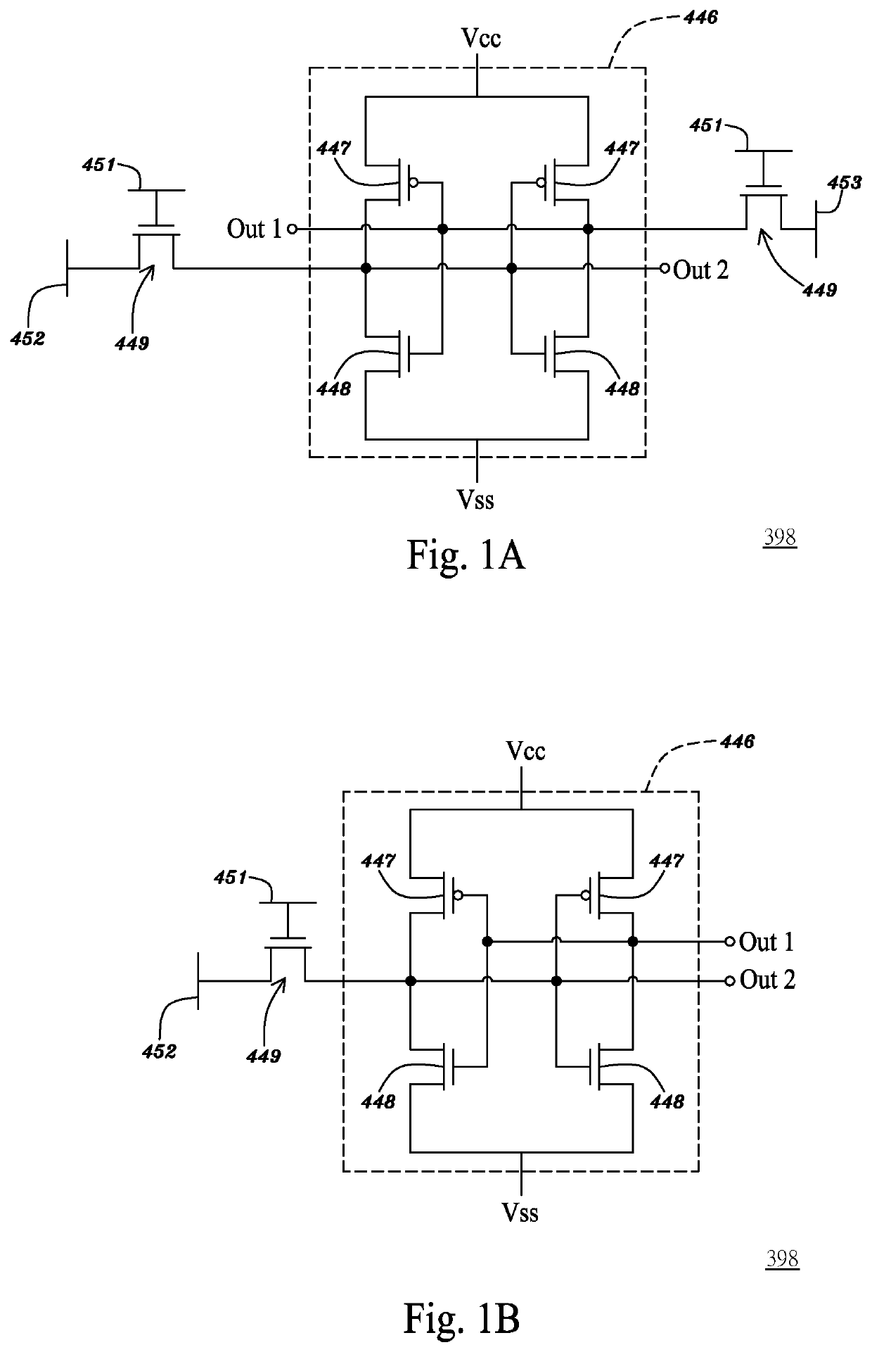
[0080]FIG. 1A is a circuit diagram illustrating a 6T SRAM cell in accordance with an embodiment of the present application. Referring to FIG. 1A, a first type of static random-access memory (SRAM) cell 398, i.e., 6T SRAM cell, may have a memory unit 446 composed of 4 data-latch transistors 447 and 448, that is, two pairs of a P-type MOS transistor 447 and N-type MOS transistor 448 both having respective drain terminals coupled to each other, respective gate terminals coupled to each other and respective source terminals coupled to the voltage Vcc of power supply and to th...


PUM


Abstract

An expandable logic scheme based on a chip package, includes: an interconnection substrate comprising a set of data buses for use in an expandable interconnection scheme, wherein the set of data buses is divided into a plurality of data bus subsets; and a first field-programmable-gate-array (FPGA) integrated-circuit (IC) chip comprising a plurality of first I/O ports coupling to the set of data buses and at least one first I/O-port selection pad configured to select a first port from the plurality of first I/O ports in a first clock cycle to pass a first data between a first data bus subset of the plurality of data bus subsets and the first field-programmable-gate-array (FPGA) integrated-circuit (IC) chip.

Description

PRIORITY CLAIM[0001]This application claims priority benefits from U.S. provisional application No. 62 / 675,785, filed on May 24, 2018 and entitled “LOGIC DRIVE WITH BRAIN-LIKE ELASTICITY AND INTEGRALITY”; U.S. provisional application No. 62 / 729,527, filed on Sep. 11, 2018 and entitled “LOGIC DRIVE WITH BRAIN-LIKE ELASTICITY AND INTEGRALITY USING STANDARD COMMODITY PROGRAMMABLE LOGIC IC CHIPS”; U.S. provisional application No. 62 / 741,513, filed on Oct. 4, 2018 and entitled “LOGIC DRIVE BASED ON STANDARDIZED COMMODITY PROGRAMMABLE LOGIC SEMICONDUCTOR IC CHIPS”; U.S. provisional application No. 62 / 755,415, filed on Nov. 2, 2018 and entitled “LOGIC DRIVE BASED ON STANDARDIZED COMMODITY PROGRAMMABLE LOGIC / MEMORY SEMICONDUCTOR IC CHIP SCALE PACKAGES”; and U.S. provisional application No. 62 / 768,978, filed on Nov. 18, 2018 and entitled “LOGIC DRIVE BASED ON STANDARDIZED COMMODITY PROGRAMMABLE LOGIC / MEMORY SEMICONDUCTOR IC CHIP SCALE PACKAGES”. The present application incorporates the foreg...

Claims


Application Information

Patent Timeline
Patent Type & Authority Applications(United States)
IPC IPC(8): H03K19/0175G06F17/50H03K19/177
CPCH03K19/1776G06F17/5054H03K19/017581H03K19/177G06F30/34
Inventor LEE, JIN-YUANLIN, MOU-SHIUNG
Owner ICOMETRUE CO LTD
Why Eureka
Try Eureka