Method for Optimizing Sensor Network Node Location in Geological CO2 Storage Area

a sensor network and geophysical technology, applied in the field of geophysical co2 storage area optimization, can solve the problems of increasing the speed of co2 /sub>emission, affecting human health, life safety and ecological environment, and limited carbon sequestration methods

Active Publication Date: 2020-01-23
CHINA UNIV OF MINING & TECH +3
View PDF3 Cites 15 Cited by
  • Summary
  • Abstract
  • Description
  • Claims
  • Application Information

AI Technical Summary

Benefits of technology

[0023]c, solving a Delaunay monitoring network optimization coverage control scheme in combination with the cluster head nodes and the sensor nodes. Advantageous Effects: In the method of the invention, an influence factor set of a leakage event is analyzed according to data in a geological CO2 storage area, such as geological data, geographical data and meteorological data, and variable density node arrangement is used to optimize wireless network sensor node arrangement schemes for different storage areas, so that the method has strong network coverage and network connectivity, and can reduce node redundancy and communication overheads. The method can reduce arrangement cost, improve monitoring quality, prolong life time, and improve timeliness, predictability and effectiveness of leakage monitoring and warning.
: In the method of the invention, an influence factor set of a leakage event is analyzed according to data in a geological CO2 storage area, such as geological data, geographical data and meteorological data, and variable density node arrangement is used to optimize wireless network sensor node arrangement schemes for different storage areas, so that the method has strong network coverage and network connectivity, and can reduce node redundancy and communication overheads. The method can reduce arrangement cost, improve monitoring quality, prolong life time, and improve timeliness, predictability and effectiveness of leakage monitoring and warning.

Problems solved by technology

Although CO2 in the atmosphere can be absorbed by vegetation, microorganisms and soil in terrestrial ecosystems, and plankton in marine ecosystems, the effects of biological and other carbon sequestration methods are very limited, so the increase speed of CO2 emission needs to be slowed down by other ways such as geological carbon sequestration.
However, maintenance of the geologically stored CO2 in a supercritical fluid state has to rely on the pressure of strata.
Once the CO2 leaks to the earth's surface through channels such as faults, fissures or oil and gas wells, gas cloud heavier than air will be formed near the earth's surface to severely affect human health, life safety and ecological environments, thus making efforts to fight global warming in vain.
The traditional network monitoring coverage control scheme often randomly or evenly arranges discrete sensor nodes in a monitoring area, but does not solve problems of node arrangement optimization of network coverage in the practical application sense, resulting in an increase and waste of detection cost.
However, the optimization method for wireless sensor network node arrangement has certain limitations in a complex geographical and geological environment of a detection area, and in the optimization method, sensors are distributed in a detection area by airdrop to determine an initial position, and scientificity and accuracy of the airdrop position are difficult to determine.
However, for a geological carbon dioxide storage monitoring sensor coverage network, due to diversification of the geological and geographical environment of the storage area, optimization of the sensor coverage network is concerned with more about different geographical and geological features of different monitoring points in the detection area, the density of monitoring point sensor network nodes, and possible interference factors of different degrees, which may not be realized by the wireless sensor network node coverage optimization method.

Method used


Image

  • Method for Optimizing Sensor Network Node Location in Geological CO2 Storage Area
  • Method for Optimizing Sensor Network Node Location in Geological CO2 Storage Area
  • Method for Optimizing Sensor Network Node Location in Geological CO2 Storage Area

Examples


Embodiment Construction

[0035]The present invention will be further described below in conjunction with the accompanying drawings.

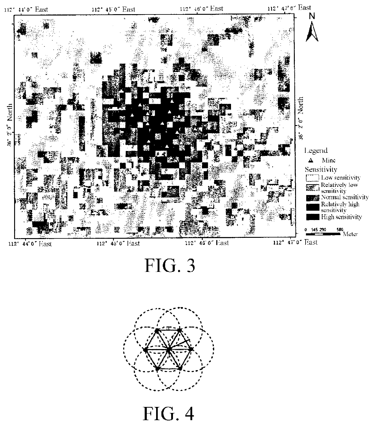
[0036]In the present invention, a coal seam CO2 injection area 5000 m*4000 m in

[0037]Qinshui Basin is used as a monitoring simulation area, grids with resolution of 100 m*100 m are used for monitoring sensitivity analysis, 14CH4 exploited wells are used as cluster head nodes for routine monitoring, sensing radii r of sensor nodes are 100 m, and a monitoring scenario is arranged according to monitoring sensitivity optimization arrangement algorithms.

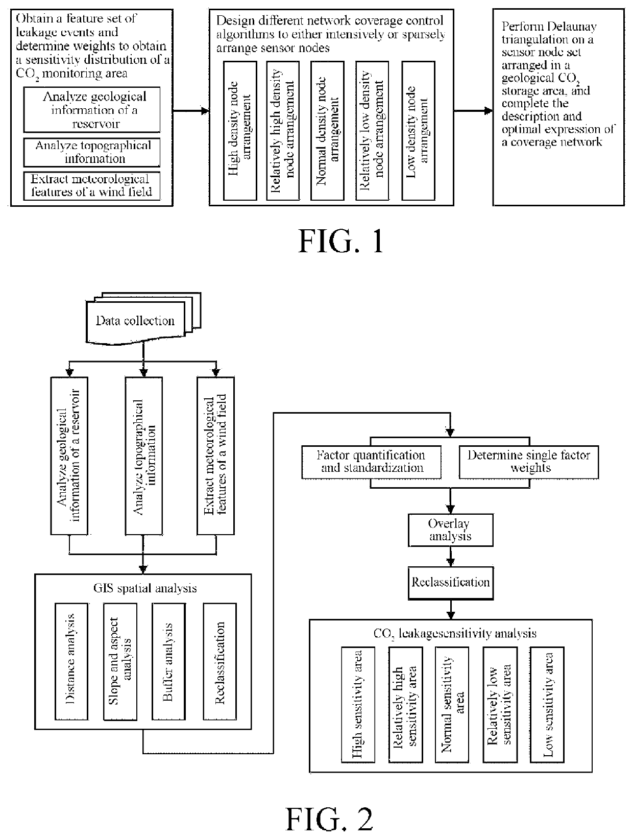
[0038]FIG. 1 shows a main flow diagram of a method for optimizing sensor network node location in geological CO2 storage area according to the present invention. First, geological, geographical and meteorological data of the geological CO2 storage area are analyzed to obtain an influence factor set of a CO2 leakage event of the geological CO2 storage area and determine weights, and then, a sensitivity distribution of the geological CO...


PUM


Abstract

The present invention discloses a method for optimizing sensor network node location in a geological CO2 storage area. In the method, by analyzing data in a monitoring area, such as geological data, geographical data, and meteorological data, analyzing influence factors of a CO2 leakage event and determining a sensitivity partition, designing different coverage control schemes of monitoring sensor network nodes, or intensively or sparsely arranging sensor monitoring nodes, a coverage network is described and optimally expressed on the basis of Delaunay triangulation. In the method for optimizing sensor network node location in a geological carbon dioxide storage area, the arrangement density of wireless sensor network nodes can be dynamically adjusted according to geological and geographical features of a detection area, and the arrangement optimization of a dynamic monitoring sensor network for coal seam carbon dioxide injection area leakage can be realized. The method reduces node redundancy and communication overheads as much as possible, and has strong network coverage and network connectivity.

Description

FIELD OF THE INVENTION[0001]The present invention relates to a wireless sensor network node location method, in particular to a method for optimizing sensor network node location in geological CO2 storage area.DESCRIPTION OF RELATED ART[0002]Global warming has attracted close attention from the international community. Carbon dioxide, as the most important greenhouse gas, is also main cause of global warming. At present, China has become the second largest emitter of CO2, will rely on non-renewable resources, especially coal, petroleum, natural gas, etc. as main energy sources for a long time, and is the potential largest emitter of CO2. Although CO2 in the atmosphere can be absorbed by vegetation, microorganisms and soil in terrestrial ecosystems, and plankton in marine ecosystems, the effects of biological and other carbon sequestration methods are very limited, so the increase speed of CO2 emission needs to be slowed down by other ways such as geological carbon sequestration. A m...

Claims


Application Information

Patent Timeline
Patent Type & Authority Applications(United States)
IPC IPC(8): E21B41/00H04W16/18H04W84/18G01V11/00G01V1/28
CPCE21B41/0064G01V1/282G01V11/00H04W16/18H04W84/18G01V9/00G01S5/00G01V99/005Y02C20/40
Inventor YANG, HUIYANG, LIFENG, GEFEIXU, XIAODONGQIN, YONGSUN, YAQINCI, HUIXUE, LIFANG
Owner CHINA UNIV OF MINING & TECH
Why Eureka
Try Eureka