Esophageal deflection device

a deflection device and esophageal technology, applied in the field of medical devices, can solve the problems of high risk of esophageal ablation, damage and death, and the deflection procedure does not ensure the displacement of the esophageal cavity, so as to achieve variable stiffness, increase density, and different stiffness

Pending Publication Date: 2020-01-30
RGT UNIV OF CALIFORNIA
View PDF0 Cites 2 Cited by
  • Summary
  • Abstract
  • Description
  • Claims
  • Application Information

AI Technical Summary

Benefits of technology

[0008]A preferred embodiment provides an esophageal deflection device. The device includes an elongate outer tube of biocompatible material having a proximal end and a distal end, the elongate outer tube being configured to contact walls of an esophagus, the elongate outer tube having a curved deflection between the distal end and the central portion, the elongate outer tube being flexible and resilient to maintain the curved deflection in a natural state and allow straightening of the elongate outer tube in response to force applied from within the elongate outer tube, the elongate outer tube being flexible enough to allow insertion and withdrawal from the esophagus, the curved deflection being stiffer than the esophagus such that the esophagus will conform to the shape of the curved deflection when the curved deflection is not straightened. The device also includes an elongate insertion tube or rod having a distal end and a proximal end, the elongate insertion tube being dimensioned to slide within the elongate outer tube, at least a portion of the elongate insertion tube being stiffer than the curved deflection of the elongate outer tube to create the force applied from within the elongate outer tube to at least partially straighten the curved deflection of the elongate outer tube when the portion of the elongate insertion tube is within the curved deflection of the elongate outer tube, the elongate insertion tube being sufficiently flexible to allow insertion into the esophagus while the portion of the elongate insertion tube is within the curved deflection of the elongate outer tube. The device preferably includes an elongate outer tube handle at the proximal end of the elongate outer tube forming a grip for a practitioner and an elongate insertion tube or rod handle at the proximal end of the elongate insertion tube or rod forming a grip for a practitioner. A length of the device is preferably predetermined to place the curved deflection at a targeted esophagus location near the left atrium of the heart. The curved deflection can be immediately adjacent the distal end of the elongate outer tube or separated by a straight portion of the elongate outer tube from the distal end of the elongate outer tube. The curved deflection can be U-shaped or is compound curve shaped. The elongate outer tube preferably includes bellows and the curved deflection includes bellows having different stiffness. A domed tip is preferably at the distal end of the elongate outer tube. The distal end of the elongate rod or tube can have a taper and the distal end and opening in the domed tip can be sized to permit a portion of the taper to extend through the opening the in the domed tip. The elongate outer tube and / or the insertion tube or rod can have a variable stiffness along. The device can include a depth insertion indicator and / or a radio opaque marker. The insertion tube or rod can have a lumen. Preferably, the outer diameter of the elongate outer tube is substantially matched to an esophagus inner diameter. Alternatively, an outer diameter of the elongate outer tube is at least half of an esophagus inner diameter. Alternatively, an outer diameter of the elongate outer tube is less than half of an esophagus inner diameter, the elongate outer tube further having suction ports for drawing a vacuum to draw esophagus walls into contact around the circumference of the elongate outer tube. Preferably, the device includes a plurality of temperature sensors disposed near an outermost surface of the elongate outer tube, which are preferably arranged in a three-dimensional pattern can be embedded in an outer coating of the elongate outer tube. The sensors are preferably arranged in orthogonal pairs along the device's longitudinal axis, exceeding the average length and area that the heart is in contact with the esophagus, and preferably increase in density in the region of curved deflection.
[0009]The invention also provides a method for conducting an esophageal deflection. The method includes inserting an insertion rod or tube into an elongate outer tube to straighten a curved deflection in the elongate outer tube. The method also includes inserting the elongate outer tube into an esophagus with the insertion rod to place the straightened curved deflection in a targeted region of the esophagus near the left atrium, and withdrawing the insertion rod or tube to allow the curved deflection to return to its natural shape and deflect the targeted region of the esophagus; wherein at least a portion of the elongate insertion tube is stiffer than the curved deflection of the elongate outer tube to create the force applied from within the elongate outer tube to at least partially straighten the curved deflection of the elongate outer tube The method can also include obtaining a three-dimensional heat map of the esophagus through a plurality of temperature sensors embedded near an outer surface of the elongate outer tube. The method can also include drawing a vacuum through a lumen in the insertion rod or tube. The method can include introducing fluids or gas through a lumen in the insertion rod or tube. The method can include drawing a vacuum through suction ports in the elongate outer tube to draw esophagus walls onto the circumference of the elongate outer tube. Preferably, the outer diameter of the elongate outer tube is substantially matched to an esophagus inner diameter. Alternatively, an outer diameter of the elongate outer tube is at least half of an esophagus inner diameter. Alternatively, an outer diameter of the elongate outer tube is less than half of an esophagus inner diameter, and the method includes drawing a vacuum through suction ports to draw esophagus walls into contact around the circumference of the elongate outer tube.

Problems solved by technology

One of the highest risks during the ablation procedure is damage to the esophagus.
Damage inflicted on esophageal cells during the ablation can lead to death.
A factor leading to damage and death has been the sensitivity of esophageal tissue to RF energy and / or heat, both of which can damage esophageal tissue directly and / or esophageal arteries.
This mechanical deflection procedure therefore does not ensure displacement of the esophagus during ablation.
Another possibility is decreased compliance of the surrounding tissues, such as the PVs and / or their antra.” In addition, initial displacements were often lost, in “most patients in this study, the esophagus assumed its original position after the endo scope was removed, as might be expected given the elastic nature of the esophageal wall and its connective tissues.
Esophageal rebound to its original position might hinder the safe delivery of radiofrequency energy.
However, there is a theoretical concern of shunting radiofrequency energy to the endoscope, which could result in thermal injury to the esophagus.”
This is complex to manufacture and use.
The force to achieve a deflection is concentrated in that area, and that concentrated force could create complications, after procedure discomfort, and could in an extreme case increase the likelihood of perforation.
Such manipulation can be inconsistent, and will also create relatively concentrated forces as discussed in the previous paragraph.

Method used


Image

  • Esophageal deflection device
  • Esophageal deflection device
  • Esophageal deflection device

Examples


Embodiment Construction

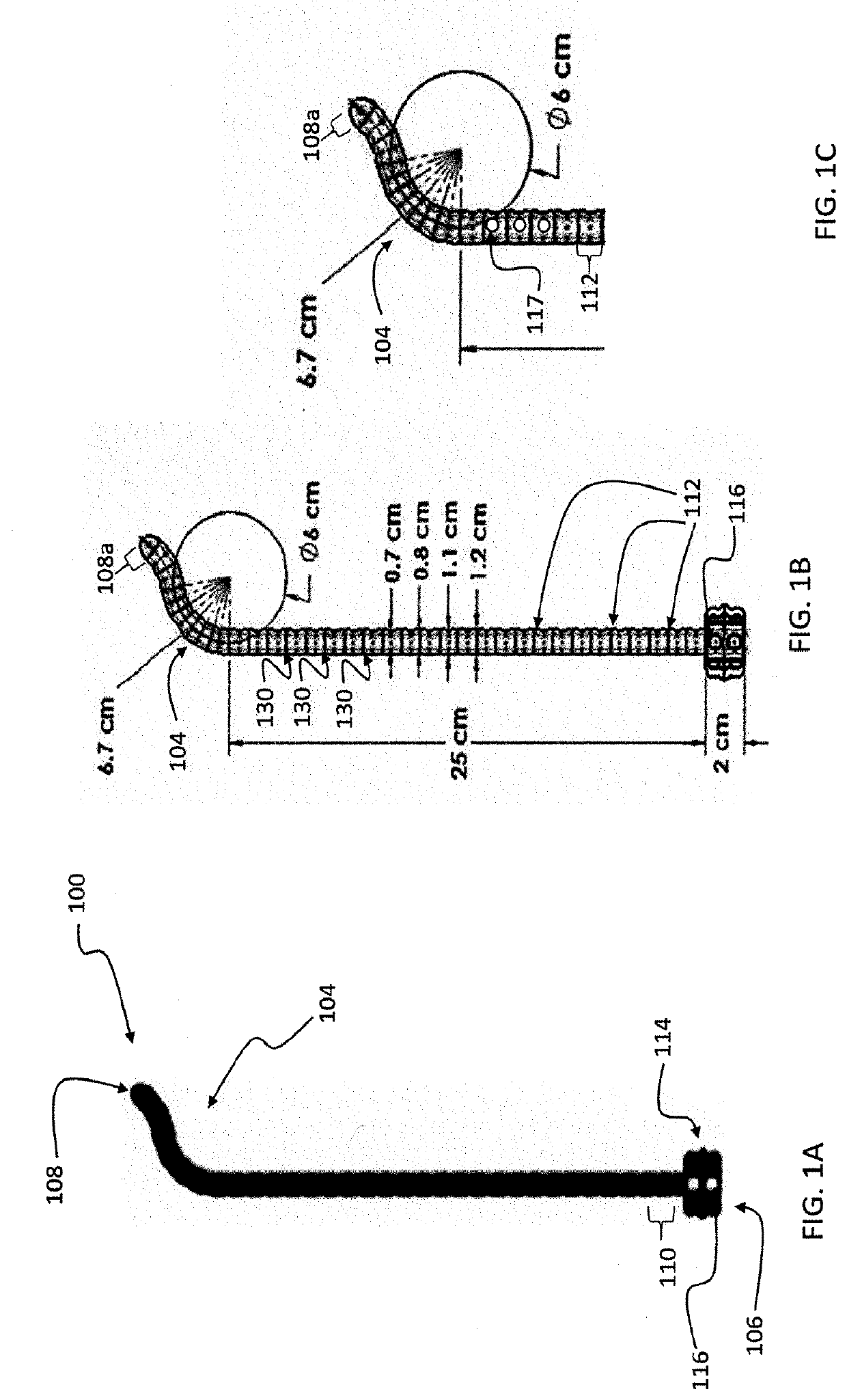
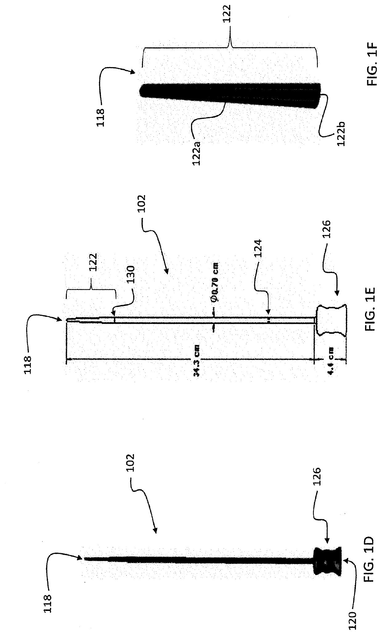
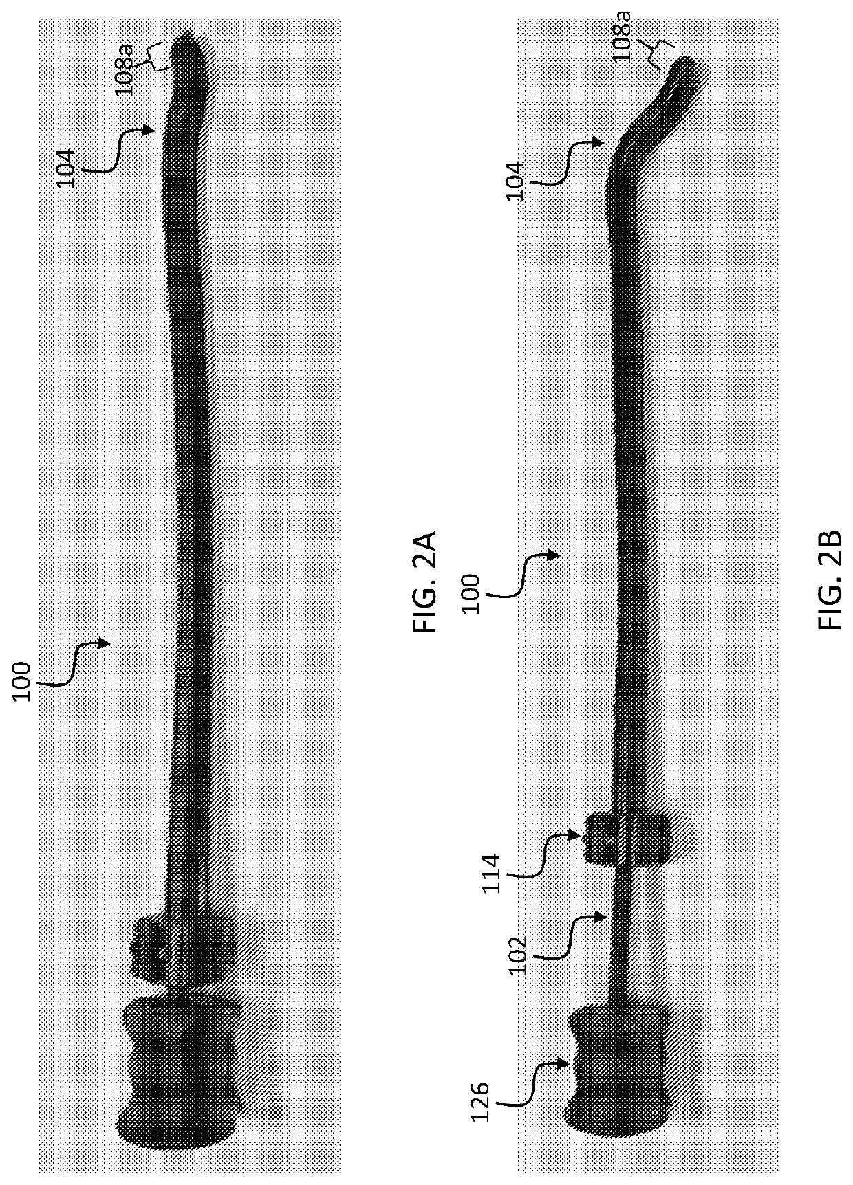
[0016]A preferred embodiment of the invention is an esophageal deflection device. The device includes a resilient outer elongate tube with a naturally curved section dimensioned and configured to insert into an esophagus and deflect the esophagus and another retractable tube or rod for reducing the curved section during insertion into the esophagus and allowing the naturally curved section of the elongate outer tube to return resiliently to its natural shape under control of a practitioner during a procedure to deflect the esophagus. In preferred embodiments, an insertion tube or rod slides within the outer elongate tube. The insertion tube or rod has portion that is stiffer than the elongate other tube.

[0017]The device can include additional features, such as a temperature probe, pressure / force sensor, or x-ray detectable insert desired at contact edge or along tube for feedback to user. By using a radio opaque material at the tip, cardiologists can use tools most familiar to them ...


PUM


Abstract

An esophageal deflection device includes an elongate outer tube that has a natural curved deflection at a position that corresponds to a targeted esophagus region for deflection. The outer diameter of the outer tube is substantially matched to an inner diameter of the esophagus to closely contact the esophagus wall, or is at least half of the inner diameter, or is smaller and includes suction ports for drawing the esophagus wall inward. An insertion rod or tube includes a portion that is stiffer than the curved deflection, and slides into the elongate outer tube to straighten the tube and can serve to guide the deflection device into an esophagus. Subsequent withdrawal of the insertion tube or rod will allow the curved deflection to return to its natural shape and deflect the targeted region of the esophagus. A three-dimensional array of temperature sensors can be disposed near an outer surface of the elongate outer tube.

Description

PRIORITY CLAIM AND REFERENCE TO RELATED APPLICATION[0001]The application claims priority under 35 U.S.C. § 119 and all applicable statutes and treaties from prior U.S. provisional application Ser. No. 62 / 468,697, which was filed Mar. 8, 2017.FIELD[0002]A field of the invention is medical devices, and particularly surgical devices. The invention provides a device that can safely deflect the esophagus during procedures. Example procedures that would benefit from the use of the device of the invention include thermal ablation of the left atrium.BACKGROUND[0003]Esophageal deflection is a critical step to certain surgical procedures. Catheter ablation is a procedure used to treat patients with refractory paroxysmal and persistent atrial fibrillation. Ablation changes electrical current paths in heart tissue by locally targeting cells that are supporting a problematic current path. In the example of ablation applied to treat arterial fibrillation, a common strategy is the creating of lesi...

Claims


Application Information

Patent Timeline
Patent Type & Authority Applications(United States)
IPC IPC(8): A61B5/01A61B5/00A61M25/00A61M25/01A61B1/005A61B1/12
CPCA61M25/0054A61M25/0108A61B5/6879A61M25/0136A61B5/01A61B5/015A61B5/687A61B5/6855A61B1/0055A61B1/128A61B17/0218A61B2017/00084A61B2017/00305A61B2017/00331A61B2017/00566A61B2017/0225A61B2017/306A61B2018/00291A61B2018/00577A61B2018/00797A61B2090/0481A61B2090/062A61B2090/08021A61B2090/0811A61B2090/3966
Inventor MORRIS, KARCHERPANDIT, ANAY MAHESHSAVIDES, THOMASSEO, YOUNGTALKE, FRANKFU, YOUYIFELD, GREGGARNER, SCOTT
Owner RGT UNIV OF CALIFORNIA
Why Eureka
Try Eureka