
Devices and methods for generating electrical current from methane

a technology of electrical current and methane, which is applied in the field of devices, can solve the problems of large greenhouse gas emissions, toxic and expensive exogenous supply of electron shuttle molecules, and damage to the atmospher

Active Publication Date: 2020-05-07
PENN STATE RES FOUND
View PDF0 Cites 3 Cited by
  • Summary
  • Abstract
  • Description
  • Claims
  • Application Information

AI Technical Summary

Benefits of technology

The present invention provides methods, microbial fuel cells, and microbial consortia for generating electrical current using a microbial consortium that includes an engineered methanogen, an exoelectrogen microbe, and a sludge or sludge isolate component. The sludge or sludge isolate component includes a microbe and / or humic acids. The microbial consortium is able to generate electrical current anaerobically. The use of the microbial consortium in a microbial fuel cell results in improved performance and stability. The invention also provides a cation exchange membrane for use in microbial fuel cells.

Problems solved by technology

However, exogenously supplied electron shuttle molecules may be toxic and expensive.
However, methane (i.e., CH4) is also a potent greenhouse gas that is more damaging to the atmosphere than carbon dioxide (i.e., CO2).
However, such processes are complex and require large-scale investment and transporting methane leads to large greenhouse gas emissions.
Therefore, processes for converting methane into liquid fuels remain a challenging area.
However, AOM is a little-understood biological process driven by natural consortia including anaerobic methanotrophic arachae (hereinafter, “ANME”) and syntrophic bacteria.
Such natural consortia of ANME and syntrophic bacteria have not been successfully isolated and separate cultivation of ANME and syncotrophic bacteria has not been reported.
Moreover, only negligible electrical current has been produced using natural uncultured anaerobic methane-oxidizing consortia isolated from oceanic sediment with methane as a substrate.

Method used


Image

  • Devices and methods for generating electrical current from methane
  • Devices and methods for generating electrical current from methane
  • Devices and methods for generating electrical current from methane

Examples


example 1

Engineering Methanosarcina acetivorans to Produce Methyl-Coenyzine Reductase

[0164]Materials and Methods. M. acetivorans strains were engineered to produce methyl-coenyzme M reductase (i.e., Mcr) from an unculturable ANME population 1 (i.e., ANME-1), identified in Black Sea mats, as described in Soo et al. Soo et al. is incorporated herein by reference in its entirety. The M. acetivorans strains employed in this Example are set forth below in Table 1 (i.e., M. acetivorans AA and M. acetivorans C2A).

TABLE 1StrainDescriptionSourceM. acetivorans AAair-adapted M. acetivoransJasso-Chavez et al.G. sulfurreducens PCAwildtype G. sulfurreducensJ. G. FerryM. acetivorans C2Awildtype M. acetivoransSowers et al.(1984) Appl.47: 971-978Plasmids (i.e.,Recombinant ExpressionCassettes)pES1(i.e., Pmat)AmpR, PurR, R6K ori, C2A ori, Pmcr—ANME-ISoo et al. (2016)15: 11pES1-MATmcr3AmpR, PurR, R6K ori, C2A ori, Pmcr—ANME-1::mcrANME-1Soo et al. (2016)15: 11

[0165]M. acetivorans AA (2 mL) and M. acetivorans C2A...

example 2

Generating a Microbial Consortium Including Engineered M. acetivorans, Geobacter sulfurreducens, and Methane-Acclimated Sludge Microorganisms

[0168]Materials and Methods Microbial Strains and Cultivation Conditions. Engineered M. acetivorans AA and M. acetivorans C2A transformed with Pmat or pES1-MATmcr3 plasmids were produced as described in Example 1. The engineered M. acetivorans AA and M. acetivorans C2A were grown anaerobically as pre-cultures at 37° C. in an 80% N2 / 19% CO2 / 1% H2 atmosphere with mild shaking in HS or HSYE medium (10 mL) with methanol (125 mM) as the carbon source, as described in Metcalf et al. (1996) J. Bacteriol. 178: 5797-5802, unless otherwise indicated. All 28-mL culture tubes (18×150 mm, Bellco Glass) were sealed by aluminum crimp seals. Pmat and pES1-MATmcr3 plasmids were maintained in the engineered M. acetivorans AA and M. acetivorans C2A with puromycin (2 μg / mL), and methane served to induce ANME Mcr production, as described in Soo et al.

[0169]Experime...

example 3

Generating MFCs Employing Microbial Consortium Including Engineered M. acetivorans, Geobacter sulfurreducens, and Sludge Microorganisms

[0174]Materials and Methods Microbial Strains and Cultivation Conditions. Engineered M. acetivorans AA, engineered M. acetivorans C2A, G. sulfurreducens PCA, and methane-acclimated sludge microorganisms were produced as described in Examples 1 and 2.

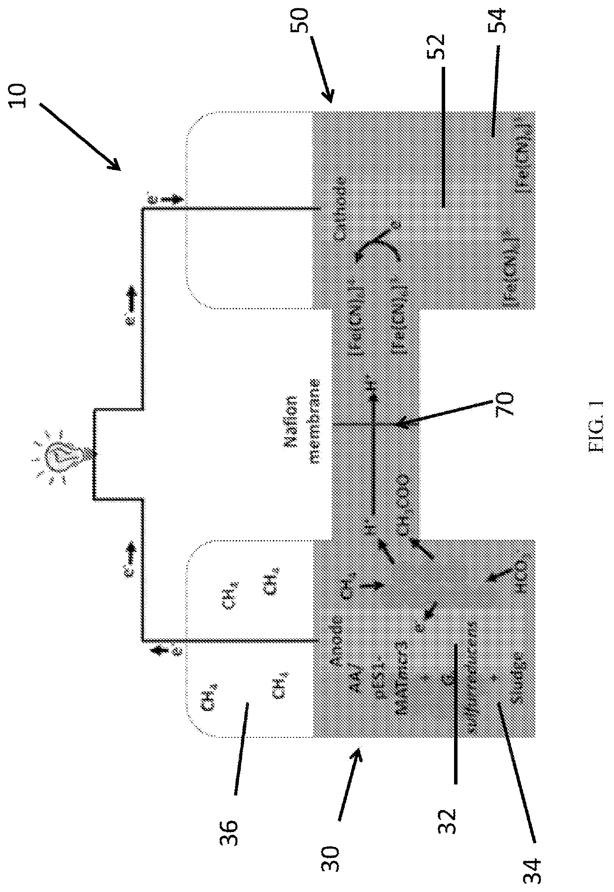
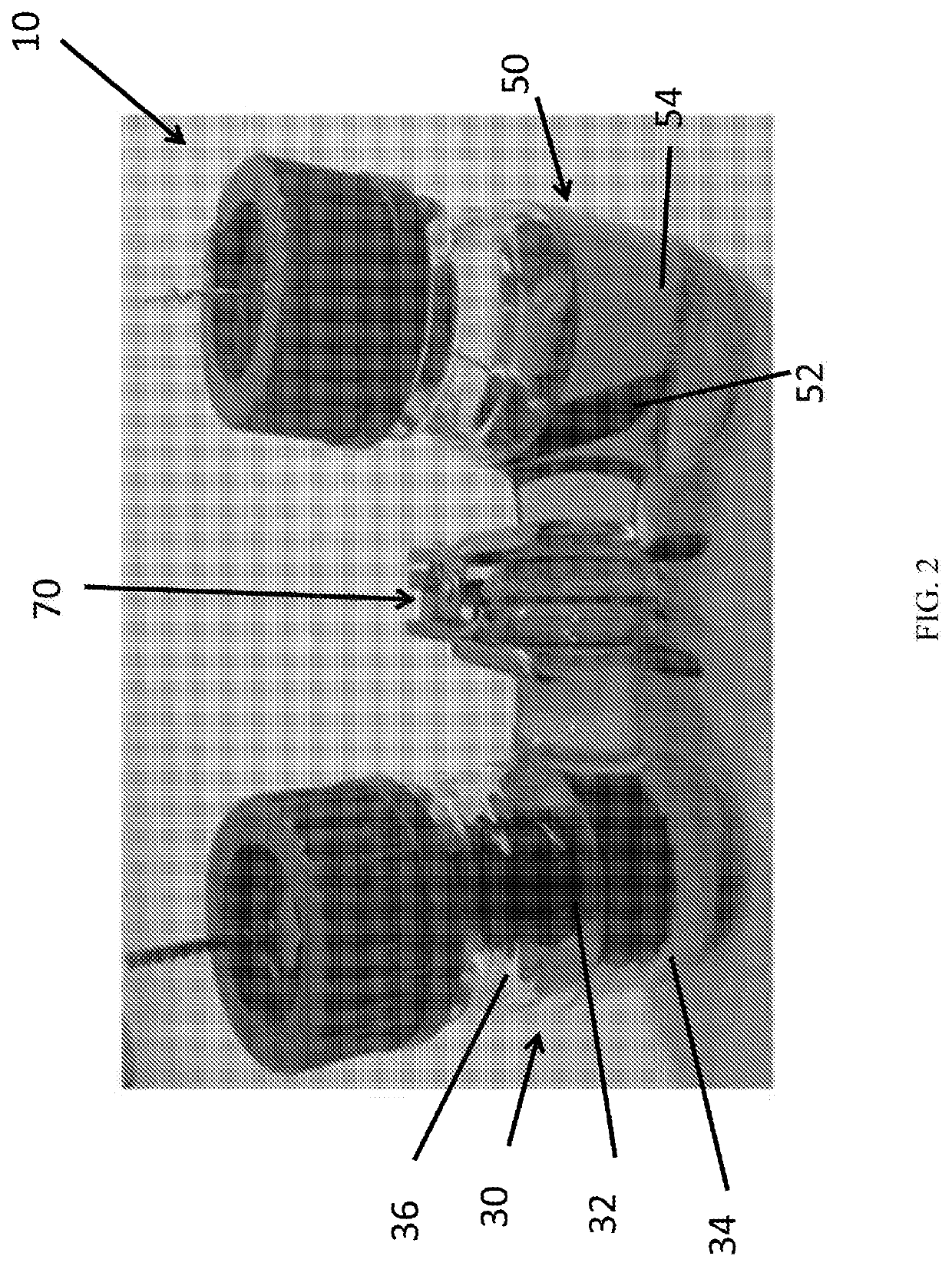
[0175]MFC Generation. Referencing FIGS. 1-2, two-bottle MFC reactors (total volume of each bottle was 155 mL) were constructed as described in Oh et al., with modifications. All MFC-related power and voltage generation results were performed with three replicates. The two bottles with sideports (2.4 cm inner diameter) were clamped together with a treated Nafion 117 proton exchange membrane (Dupont, Wilmington, Del.) and one rubber gasket (3.5 cm outer diameter). The Nafion 117 membranes were cut into 4×4 cm squares, then pre-treated by heating for 1 hr in solutions of hydrogen peroxide (30%), sulfuric aci...


PUM

PropertyMeasurementUnit
timeaaaaaaaaaa
surface areaaaaaaaaaaa
timeaaaaaaaaaa

Abstract

Methods, microbial fuel cells and microbial consortia for generating electrical current are provided according to the present invention which include providing a microbial consortium to an anode chamber of a microbial fuel cell, wherein the microbial CN consortium includes: 1) an engineered methanogen that contains a heterologous nucleic acid sequence encoding methyl-coenzyme M reductase derived from an anaerobic methane oxidizer, 2) an exoelectrogen microbe that produces electrically-conductive appendages and / or one or more types of electron carrier, and 3) a sludge, methane-acclimated sludge, a sludge isolate component, a methane-acclimated sludge isolate component chosen from Paracoccus spp., Geotoga spp., Geobacter spp., Methanosarcina spp., Garciella spp., humic acids; or a combination of any two or more thereof.

Description

REFERENCE TO RELATED APPLICATIONS[0001]This application claims priority to U.S. Provisional Patent Application Ser. Nos. 62 / 425,421, filed Nov. 22, 2016 and 62 / 445,871 filed Jan. 13, 2017, the entire content of both of which is incorporated herein by reference.GOVERNMENT SUPPORT[0002]This invention was made with government support under Grant No. DE-AR0000431 awarded by the Department of Energy. The Government has certain rights in the invention.SEQUENCE LISTING[0003]The instant application contains a Sequence Listing which has been submitted electronically in ASCII format and is hereby incorporated by reference in its entirety. Said ASCII copy, created on Jan. 7, 2020, is named 36PST86402PA_ST25.txt and is 18.5 kilobytes in size.FIELD OF THE INVENTION[0004]Methods, systems and microbial consortia of the present invention are described herein which relate generally to microbial fuel cells. Methods, systems and microbial consortia of the present invention are described herein which r...

Claims


Application Information

Patent Timeline
Patent Type & Authority Applications(United States)
IPC IPC(8): H01M8/16H01M8/0662C12P5/02C12N1/20H01M4/96
CPCH01M8/16H01M4/96C12P5/023H01M8/0687C12N1/20C12N9/13Y02E60/50Y02E50/30
Inventor WOOD, THOMAS K.MCANULTY, MICHAEL J.
Owner PENN STATE RES FOUND
Learn More