

Method for Exhaust Waste Energy Recovery at the Reciprocating Gas Engine-based Polygeneration Plant
- Summary
- Abstract
- Description
- Claims
- Application Information
AI Technical Summary
Benefits of technology
Problems solved by technology
Method used
Image

Examples
Embodiment Construction
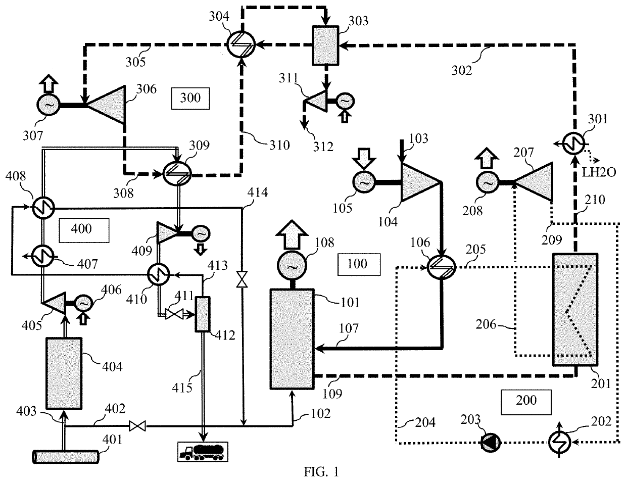
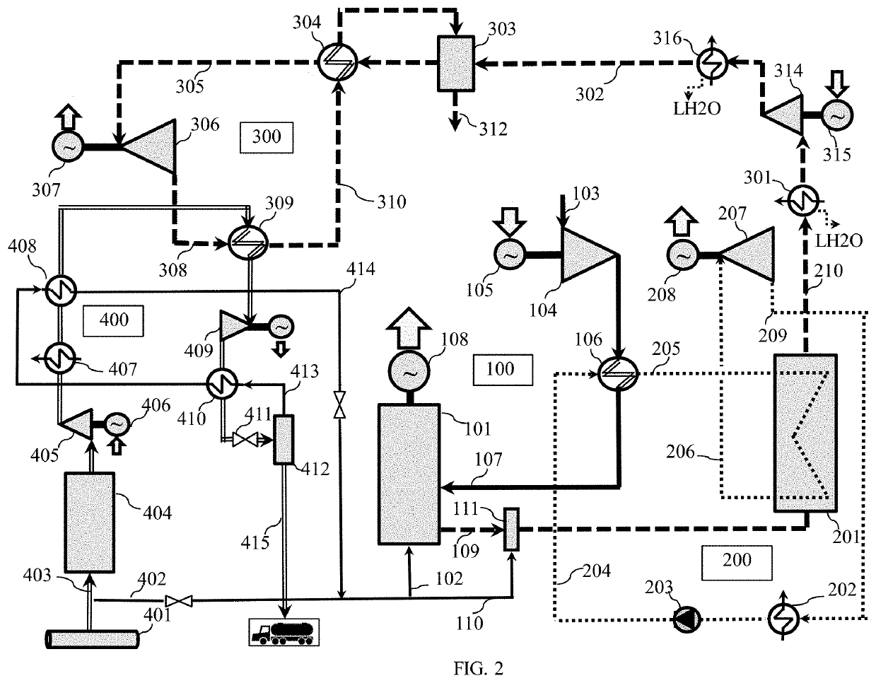
[0034]The practical realization of the proposed method for exhaust waste energy recovery at the reciprocating gas engine-based polygeneration (GPG) plant may be performed through an innovative use of gas engine exhaust for liquefying most of the methaneous gaseous fuel (pipeline natural gas, biogas, landfill gas, coal-bed methane and renewable methane) delivered into such plant. By this means the GPG plant may be used for co-production of power and liquefied methaneous gas (LMG); in so doing on-site liquefaction of methaneous gas at the GPG plant in the wide range of LMG co-product pressure is distinguished from LMG production at the specialized small-scale plants by much greater simplicity of the proposed process and its much higher efficiency. Taking into account that the energy and pre-treatment costs are particularly high at the small-scale LMG plants and that the invented method may drastically reduce these costs, it may be especially promising for co-production of the LMG at a...
PUM
 Abstract
Description
Claims
Application Information