
Dual parallel optical axis modules sharing sample stage for bioburden testing

Inactive Publication Date: 2020-06-11
REAMETRIX
View PDF0 Cites 5 Cited by
  • Summary
  • Abstract
  • Description
  • Claims
  • Application Information

AI Technical Summary

Benefits of technology

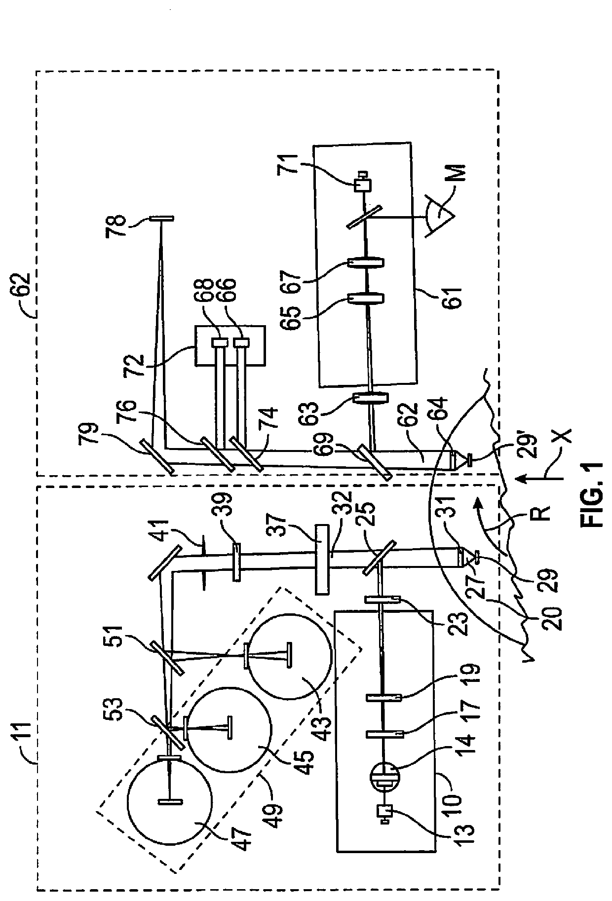
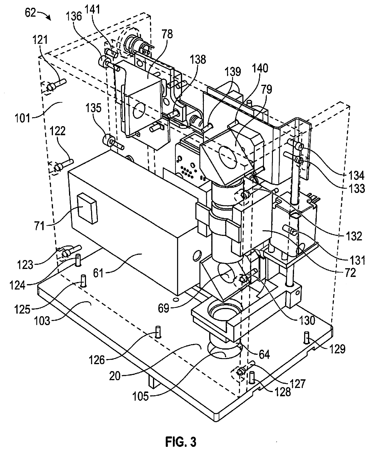
The patent describes a device that has two parallel optical axes that can inspect samples for bioburden. The device uses a first optical axis to create a fluorescent illumination of the sample, while a second optical axis images the location of the illuminated sample. The device can identify bioburden targets quickly using a low resolution scan and then perform a high resolution scan to inspect the size and morphology of the targets. The device can be easily moved around in a laboratory or manufacturing facility. The technical effect is that the device enables fast and accurate inspection of samples for bioburden.

Problems solved by technology

Nevertheless, the main challenge is not to only produce a quicker method of analysis, but also to ensure that the sensitivity of detection is maximized, i.e, the technology has the ability to detect very low levels of microorganisms, even down to a single bacterium for sterility testing.
A problem that occurs in prior art assays based on fluorescence is false positive readings since background fluorescence is ubiquitous.

Method used


Image

  • Dual parallel optical axis modules sharing sample stage for bioburden testing
  • Dual parallel optical axis modules sharing sample stage for bioburden testing
  • Dual parallel optical axis modules sharing sample stage for bioburden testing

Examples


Embodiment Construction

[0021]With reference to FIG. 1, a laser fluorescence excitation module 11 follows previously mentioned U.S. Pat. No. 9,709,500, incorporated by reference herein, and includes dual laser diode light source 13, having selectable laser diodes generating an incident beam on a sample carrier with wavelengths of between 480 nm to 500 nm at 12 mv and alternatively at 625 nm at 13 mv. This is followed by collimation optics 14, 17, 19 to produce a beam 21 having a diameter to impinge on the sample through collimator 23 and tilted glass plate 25. The beam yields a laser spot 27 of about 6 microns that defines a sample probe area 29 on the spinning sample carrier 20 for stimulating fluorescence along the first optical axis 32. The spot has a large depth of focus, say plus or minus 36 microns and the membrane does not have to be in perfect focus.

[0022]An excitation wavelength of 488 nm will excite fluorescence in sample material in a 30 nm band centered on 525 nm, 570 nm and 625 nm using three ...


PUM


Abstract

Filter membranes and the like carrying fluorescent targets suspected of being bioburden are tested by mounting the membranes on a sample holder within a cabinet for bioburden verification and discrimination from false positives. Fluorescence is excited by a fluorescence excitation module having a first optical axis perpendicular to the sample, with three dimension locations of fluorescent targets that are probable bioburden stored for use by a microscope imaging module having a second optical axis parallel to the first optical axis, with dual wavelength illumination for autofocus and then for stimulating fluorescence without photo bleaching of the targets. The probable bioburden targets are moved for inspection and identification in the microscope imaging module as bioburden or not by sharing a common sample holder in the cabinet.

Description

CROSS-REFERENCE TO RELATED APPLICATION[0001]This application claims priority under 35 U.S.C. 119(e) from prior U.S. provisional application 62 / 777,938, filed Dec. 11, 2018.TECHNICAL FIELD[0002]The invention relates to sterility and bioburden testing of fluorescent samples and, more particularly, to rapid fluorescent analysis of filter membranes or flat fluid samples for sterility and bioburden testing.BACKGROUND ART[0003]In the pharmaceutical industry, quality control laboratories are monitoring sterility or bioburden in non-sterile fluids under strong pressure to reduce the time for testing microbiological contamination due to increasing demands for fast results. Prior art use of standard agar growth plates for detection and enumeration of bacteria and the like typically takes 3-5 days.[0004]In order to improve the ability to detect non-sterile conditions, manufacturers have looked towards new technologies to reduce the time for sample analysis. Nevertheless, the main challenge is ...

Claims


Application Information

Patent Timeline
IPC IPC(8): G02B21/00G01N21/64G02B21/36
CPCG02B21/0076G01N21/6458G02B21/06G02B21/365C12Q1/22G01N21/6486
Inventor MANIAN, BALA S.
Owner REAMETRIX
Learn More