Source Module and Optical System For Line-Field Imaging

Active Publication Date: 2020-06-25
EXALOS
View PDF0 Cites 6 Cited by
  • Summary
  • Abstract
  • Description
  • Claims
  • Application Information

AI Technical Summary

Benefits of technology

[0012]Embodiments of the invention are capable of providing improved line-field illumination schemes by exploiting the intrinsic anamorphic beam properties of edge-emitting semiconductor sources such as light emitting diodes including organic light emitting diodes, superluminescent diodes, lasers and so forth. Although an elliptical profile causes loss of light when coupled into a single mode fiber, from its geometry it is intrinsically better suited to line illumination schemes. In contrast, when

Problems solved by technology

This can however only be achieved in full-field OCT by using expensive high-speed sensor technology.
In addition, full-field OCT lacks the confocal gating, that helps to suppress out-of-focus light that otherwise reduces the dynamic range of the sensor and ulti

Method used


Image

  • Source Module and Optical System For Line-Field Imaging
  • Source Module and Optical System For Line-Field Imaging
  • Source Module and Optical System For Line-Field Imaging

Examples


Embodiment Construction

[0033]When describing an ellipse or elliptical shape we use the parameters ‘a’ and ‘b’ for the diameters of the major and minor axes of the ellipse. Their ratio a / b is referred to as the aspect ratio of the ellipse. While a circle can be defined as an ellipse with a unitary aspect ratio, i.e. a / b=1, for the purposes of this document, we do not consider a circle to be an ellipse, i.e. by ‘ellipse’ or ‘elliptical’ we mean an ellipse with a non-unitary aspect ratio.

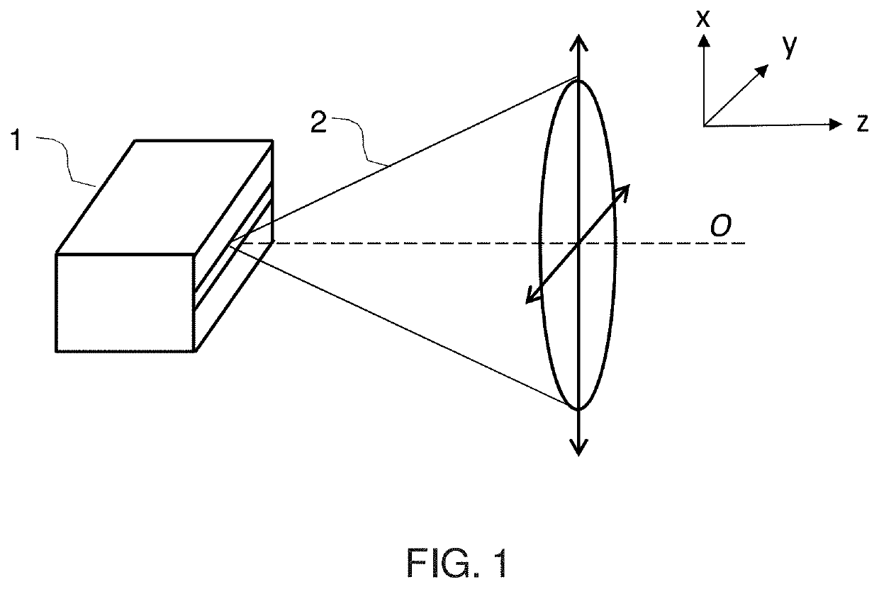
[0034]FIG. 1 is a schematic drawing of a generic semiconductor source 1 and the divergent elliptical beam shape 2 of its output. The semiconductor chip of the source is made of epitaxial layers extending in the yz-planes as schematically depicted. The illustrated output face of the chip is in the xy-plane. The source's output beam 2 is of elliptical shape in the far field, with the major (i.e. long) axis of the ellipse being in the x-direction, the minor (i.e. short) axis in the y-direction, and the optical axis O of the out...


PUM


Abstract

A source module suitable for an optical coherence tomography system. The source module comprises a source operable to emit a divergent, source output beam either of circular cross-section (e.g. as output by a vertical cavity surface emitting laser) or of elliptical cross-section (e.g. as output by an edge-emitting semiconductor laser or diode). Collimation optics are provided to convert the source output beam into a non-divergent, collimated beam of elliptical cross-section having a major axis and a minor axis. A cylindrical lens is arranged with its plano axis aligned with the major axis of the elliptical collimated beam and its power axis aligned with the minor axis of the elliptical collimated beam so as to form a line focus extending along the major axis of the elliptical collimated beam.

Description

CROSS-REFERENCE TO RELATED APPLICATIONS[0001]This non-provisional patent application claims the benefit of and priority to U.K. Patent Application No. 1820792.8, filed Dec. 20, 2018, which is incorporated herein by reference in its entirety.STATEMENT REGARDING FEDERALLY SPONSORED RESEARCH OR DEVELOPMENT[0002]Not ApplicableREFERENCE TO SEQUENCE LISTING, A TABLE, OR A COMPUTER PROGRAM LISTING COMPACT DISC APPENDIX[0003]Not ApplicableFIELD OF THE INVENTION[0004]The invention relates to line-field illumination systems that use light from semiconductor light sources, such as light emitting diodes, semiconductor lasers, swept source semiconductor lasers and superluminescent diodes.BACKGROUND OF THE INVENTION[0005]Acquisition speeds have been advancing rapidly in modern imaging techniques. For example, in optical coherence tomography (OCT) acquisition speed has increased by several orders of magnitude during the last decade. Today, recently-developed laser sources allow even MHz “A-scan” r...

Claims


Application Information

Patent Timeline
IPC IPC(8): G02B27/09G02B27/30F21V8/00G01N15/14G01B9/02
CPCG02B27/0977A61B3/102G01N15/1436G01B9/02091G02B27/0916G02B6/003G02B27/30G02B27/0966G01B9/02037G02B19/0014G02B19/0052G02B27/0911H01S3/005A61B5/0066
Inventor GINNER, LAURINLEITGEB, RAINERDÜLK, MARCUS
Owner EXALOS
Why Eureka
Try Eureka