
Method of manufacturing deep ultraviolet light emitting device

a technology of light emitting devices and manufacturing methods, which is applied in the manufacturing of semiconductor/solid-state devices, semiconductor devices, electrical devices, etc., can solve the problems of reducing the operation voltage is reduced, and the device is driven by an extremely high operating voltage, so as to reduce the contact resistance of the n-side electrode, reduce the series resistance of the light emitting device, and facilitate proper ohmic contact

Active Publication Date: 2020-07-02
NIKKISO COMPANY
View PDF0 Cites 0 Cited by
  • Summary
  • Abstract
  • Description
  • Claims
  • Application Information

AI Technical Summary

Benefits of technology

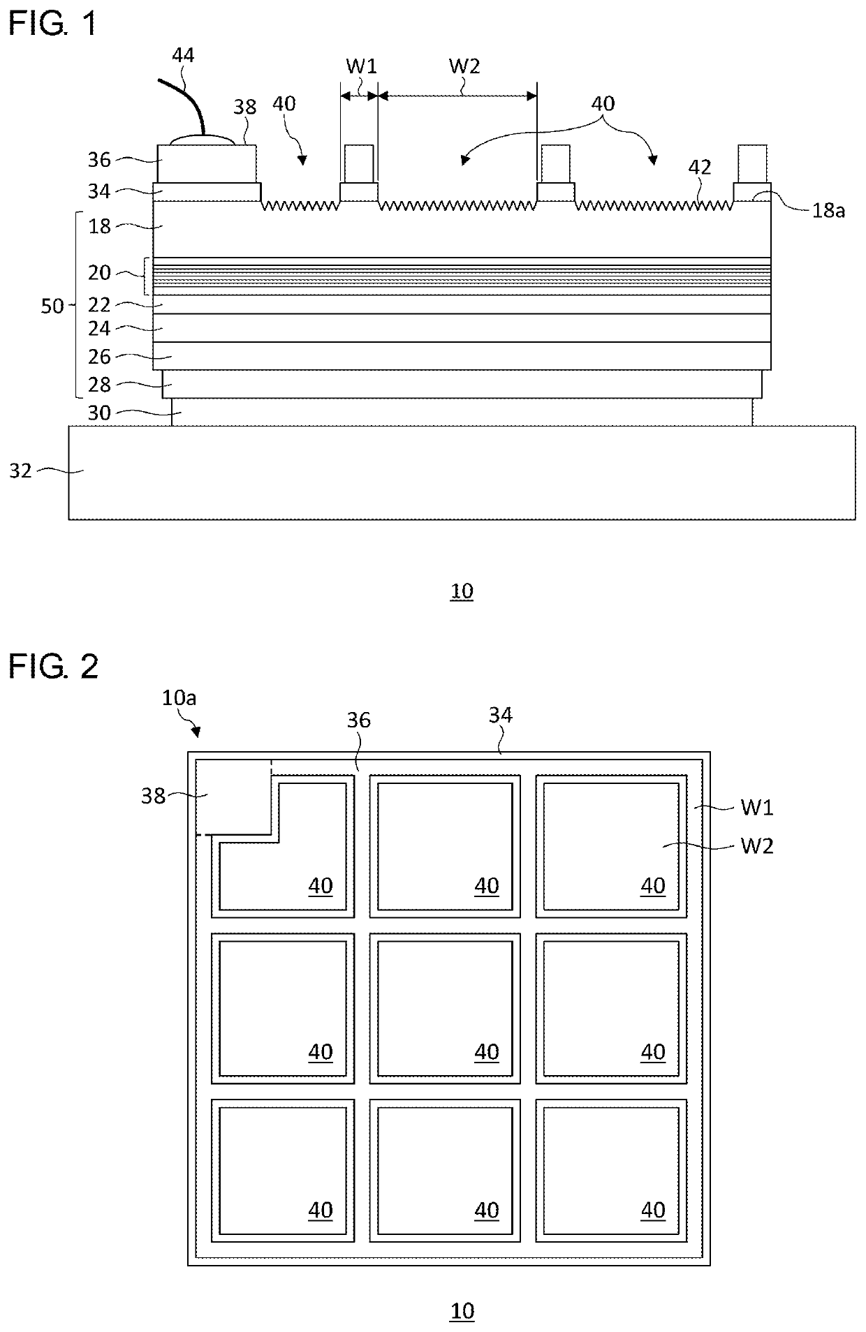
[0010]According to this embodiment, since the n-side electrode is formed via the n-type contact layer having a smaller band gap than the n-type clad layer, the contact resistance of the n-side electrode is lowered. Further, by forming the n-side electrode on the n-type contact layer, it is easier to realize appropriate ohmic contact as compared with the case of forming the n-side electrode on the n-type clad layer of an AlGaN-based semiconductor material. This reduces the series resistance of the light emitting device and realizes a low operating voltage.
[0015]According to this embodiment, since the n-side electrode is formed via the n-type contact layer having a smaller band gap than the n-type clad layer, the contact resistance of the n-side electrode is lowered. Further, by forming the n-side electrode on the n-type contact layer, it is easier to realize proper ohmic contact as compared with the case of forming the n-side electrode on the n-type clad layer of an AlGaN-based semiconductor material. This reduces the series resistance of the light emitting device and reduces an operating voltage.
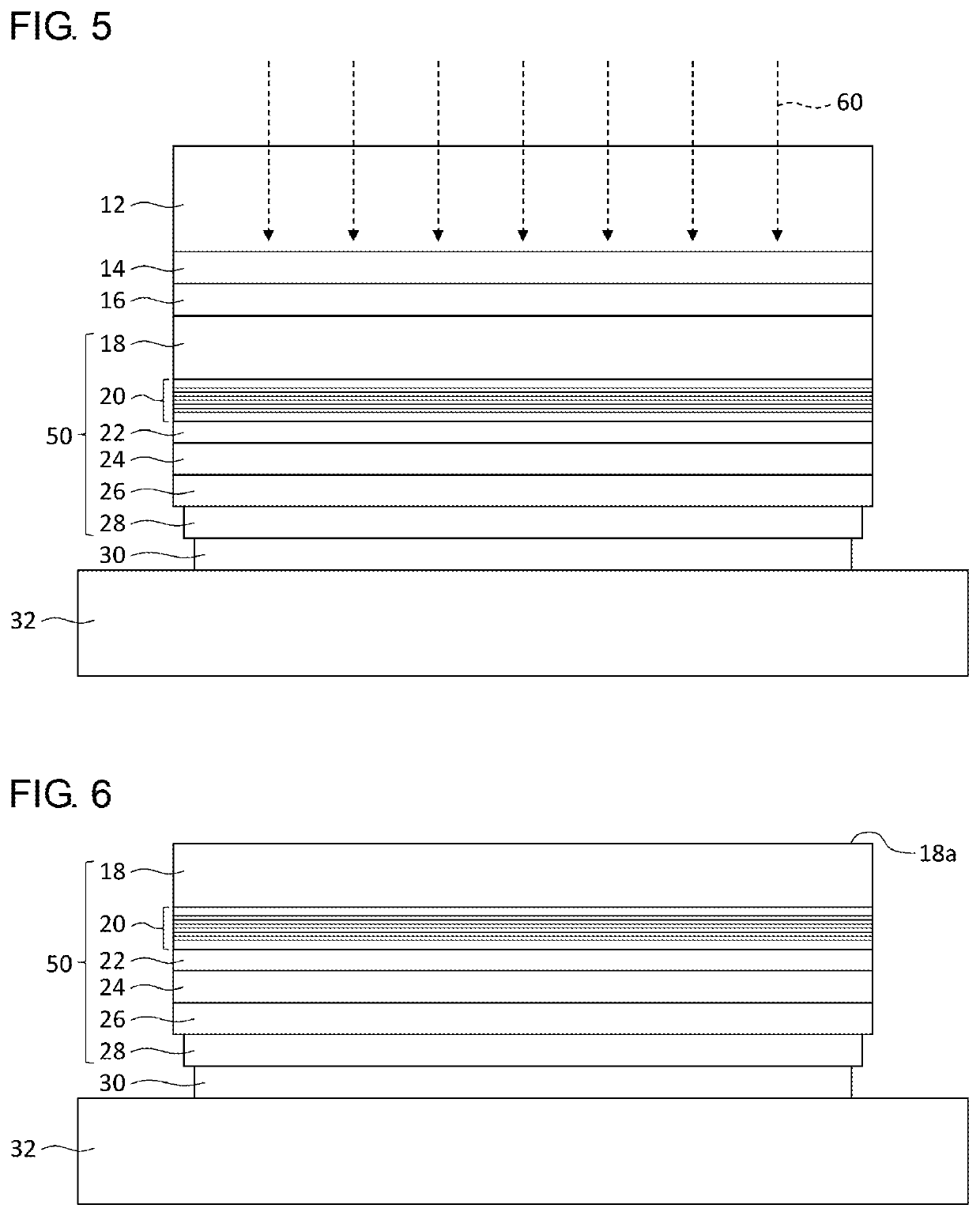
[0016]The forming an n-type contact layer may include: forming a mask, avoiding the partial region on the n-type clad layer exposed by removing the base substrate; forming the layer of an n-type semiconductor material on the mask; and removing the mask to form an opening region on the n-type clad layer.

Problems solved by technology

However, according to the non-patent document 1, the series resistance between the n-side electrode and the p-side electrode in the light emitting device of vertical structure is large and an extremely high operating voltage is necessary to drive the device to produce a high output.
This reduces the series resistance of the light emitting device and reduces an operating voltage.

Method used


Image

  • Method of manufacturing deep ultraviolet light emitting device
  • Method of manufacturing deep ultraviolet light emitting device
  • Method of manufacturing deep ultraviolet light emitting device

Examples


Embodiment Construction

[0033]The invention will now be described by reference to the preferred embodiments. This does not intend to limit the scope of the present invention, but to exemplify the invention.

[0034]A description will be given of an embodiment of the present invention with reference to the drawings. Like numerals are used in the description to denote like elements and the description is omitted as appropriate. To facilitate the understanding, the relative dimensions of the constituting elements in the drawings do not necessarily mirror the relative dimensions in the actual apparatus.

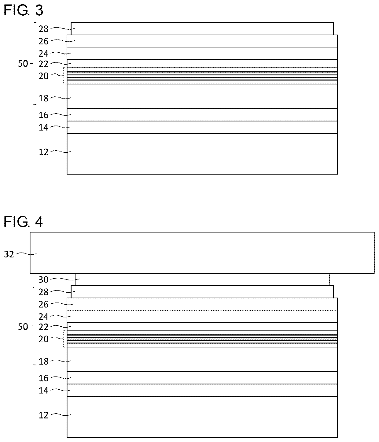
[0035]FIG. 1 is a cross sectional view schematically showing a configuration of a deep ultraviolet light emitting device 10 according to the embodiment. The deep ultraviolet light emitting device 10 includes a support substrate 32, an adhesive layer 30, a p-side electrode 28, a p-type contact layer 26, a p-type clad layer 24, an active layer 20, an n-type clad layer 18, an n-type contact layer 34, and an n-side ele...


PUM

PropertyMeasurementUnit
central wavelengthaaaaaaaaaa
band gapaaaaaaaaaa
central wavelengthaaaaaaaaaa

Abstract

A deep ultraviolet light emitting device includes: an electron block layer of a p-type AlGaN-based semiconductor material or a p-type AlN-based semiconductor material provided on a support substrate; an active layer of an AlGaN-based semiconductor material provided on the electron block layer; an n-type clad layer of an n-type AlGaN-based semiconductor material provided on the active layer; an n-type contact layer provided on a partial region of the n-type clad layer and made of an n-type semiconductor material containing gallium nitride (GaN); and an n-side electrode formed on the n-type contact layer. The n-type contact layer has a band gap smaller than that of the n-type clad layer.

Description

RELATED APPLICATION[0001]This application is a Divisional of co-pending application Ser. No. 16 / 177,945, filed on Nov. 1, 2018, which is a continuation of International Patent Application No. PCT / JP2017 / 014237, filed on Apr. 5, 2017, for which priority is claimed under 35 U.S.C. § 120; and this application claims priority of Application No. 2016-092617 filed in Japan on May 2, 2016 under 35 U.S.C. § 119, the entire contents of all of which are hereby incorporated by reference.BACKGROUND1. Field of the Invention[0002]The present invention relates to deep ultraviolet light emitting devices, and, more particularly, to a deep ultraviolet device in which a nitride semiconductor is used and a method of manufacturing such a device.2. Description of the Related Art[0003]Nowadays, semiconductor light emitting devices such as light emitting diodes and laser diodes that emit blue light have been in practical use. Development of light emitting devices that output light having a shorter waveleng...

Claims


Application Information

Patent Timeline
Patent Type & Authority Applications(United States)
IPC IPC(8): H01L33/00H01L33/22H01L33/06H01L33/32H01L33/38
CPCH01L33/387H01L33/32H01L33/22H01L33/06H01L33/0025H01L33/0075H01L33/38H01L2933/0016H01L33/40H01L21/205H01L33/0008H01L33/005H01L33/14
Inventor INAZU, TETSUHIKOPERNOT, CYRIL
Owner NIKKISO COMPANY
Learn More