Desalting plant systems and methods for enhanced tight emulsion crude oil treatment

a technology of tight emulsion crude oil and desalting plant, which is applied in the direction of water/sludge/sewage treatment, separation processes, chemical instruments and processes, etc., can solve the problems instability and safety hazards, etc., and achieve the reduction of the effect of reducing the risk of transformer short-circuiting and tripping

Active Publication Date: 2020-08-13
SAUDI ARABIAN OIL CO
View PDF0 Cites 5 Cited by
  • Summary
  • Abstract
  • Description
  • Claims
  • Application Information

AI Technical Summary

Benefits of technology

[0008]Disclosed are systems and processes to continuously or discontinuously extract and treat, reduce, or prevent an emulsion rag layer frequently formed at oil-aqueous liquid interfaces within crude oil separation and treatment equipment, such as for example desalters, dehydrators, and wet crude oil tanks, such as low pressure degassing tanks. In some embodiments, the treatment is accomplished by continuously feeding a slip stream from an emulsion rag layer through a restricted orifice (RO) into a three-phase separation vessel or spool of pipe fitted with fully insulated electrostatic electrodes to break the emulsion. By enabling efficient control, reduction, and elimination of the rag layer in separation vessels such as for example dehydrators and desalters, the risk of transformer short-circuiting and tripping is reduced with respect to insulated electrostatic electrode grids in the vessels.
[0009]One objective is to reduce, limit, or prevent the growth of the emulsion rag layer in crude oil treatment vessels by continuously withdrawing a slip stream of the emulsion layer and treating it. Suitable insulated electrostatic electrodes are capable of handling up to 100% water cut without short circuiting, and this enhances the emulsion breaking capabilities. Limiting and treating the emulsion rag layer will avoid off-specification crude oil products and minimize demulsifier and wash water consumption. In embodiments of the disclosure, systems and methods enable the efficient control, reduction, in addition to or alternative to elimination of the rag layer. Embodiments of the disclosure can separate up to about 90% of the water content in the rag layer depending on operating temperature, crude type, electrostatic coalescers and demulsifier used, or alternatively up to about or greater than about 95% of the water content in the rag layer.
[0010]In some embodiments, targeted crude oil specifications include a salt content of not more than 10 lbs. of salt / 1,000 barrels (PTB) and a BSW of not more than 0.3 volume percent. Continuously withdrawing and treating a rag layer from crude oil treatment units such as dehydrators and desalters using fully insulated electrostatic electrodes fitted inside a 3-phase separation vessel or spool of pipe includes the following advantages: processes are independent of the interface level measurement as it will limit the maximum interface level automatically by continuously withdrawing the liquid from the interface point; withdrawn liquids can be an emulsion, dry crude, or 100% water; embodiments of the systems and methods disclosed can handle 100% water, gas, or oil; embodiments of systems and methods are used to control the maximum water level inside units such as desalters and dehydrators to avoid arcing or short-circuiting and, consequently, off-specification crude oil.
[0011]In some embodiments, the level of growth of the rag layer is controlled by continuously removing the rag layer formed from a given vessel. Therefore, the interface level can be controlled without having to measure it because the layer is continuously removed. In some embodiments, the fluid is continuously withdrawn using differential pressure. Dehydrators and desalters typically operate at higher pressures than a separation vessel, such as for example a low pressure degassing tank (LPDT). The fluid inside the dehydrators and desalters can be continuously withdrawn using the differential pressure between greater pressure vessels, such as for example dehydrators, and lesser pressure vessels, such as for example a LPDT.
[0013]The implementation of embodiments of systems and methods of the present disclosure will help avoid off-specification crude oil; reduce demulsifier chemical consumption and wash water consumption (lower operating cost); increase the capacity of existing desalters to de-bottleneck plant capacity; reduce the size for new desalter and dehydrators (lower capital cost); will be used to control the maximum water level inside desalters and dehydrators to avoid arcing or short-circuiting and consequently off-specification crude oil; minimize the dependency on liquid interface measurements to control the interface level; and minimize the dependency on operator to monitor the interface measurements to control the rag layer.
[0014]Embodiments described here withdraw more frequently or continuously the rag layer from GOSP units such as for example desalters and dehydrators at a controlled rate to maintain the interface level using a restricted orifice (RO) or a control valve in combination with reliable interface measurements, such as with a level indicator and controller (LIC) in addition to or alternative to a flow indicator and controller (FIC). LIC's as described herein can be used in combination with control valves in addition to or alternative to flow indicators and controllers. A rag layer stream can be fed into either or both a three phase separator vessel with fully insulated electrostatic electrodes inside to separate oil, gas, and water and a two phase vessel to aid in breaking the emulsion. In some embodiments, when the electrodes are 100% deactivated, this would indicate about 100% water cut from a slip stream intending to withdraw a rag layer, but instead only withdrawing water. Therefore, it could be used as indicator to troubleshoot / enhance the desalting process and control the water level.

Problems solved by technology

However, a large pressure reduction in a single separator will cause flash vaporization, leading to instability and safety hazards.
Prior art GOSP systems also suffer from the following issues: transformer tripping and inefficient energy usage; off-specification crude oil production in terms of BSW and salt content; high operating costs required to meet the crude specifications; and inefficient human and manual operations.
Certain prior art treatments are limited to treating crude oil with a low water cut (approximately 30% by volume), while water cut in certain emulsion layers can reach as high as about 85% for tight emulsions in heavy crude oil applications.
Rag layers grow and consequently reduce the efficiency and effectiveness of the desalting and dehydrating processes in GOSP systems.
Failure to control the rag layer can result in off-specification product in terms of salt content and BSW, because when the rag layer comes into contact with the electrical grids of the electrostatic electrodes of a dehydrator or desalter, this will cause short-circuiting and tripping of the transformers.

Method used


Image

  • Desalting plant systems and methods for enhanced tight emulsion crude oil treatment
  • Desalting plant systems and methods for enhanced tight emulsion crude oil treatment
  • Desalting plant systems and methods for enhanced tight emulsion crude oil treatment

Examples


Embodiment Construction

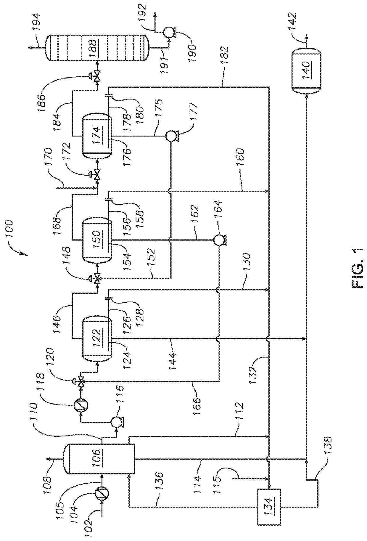
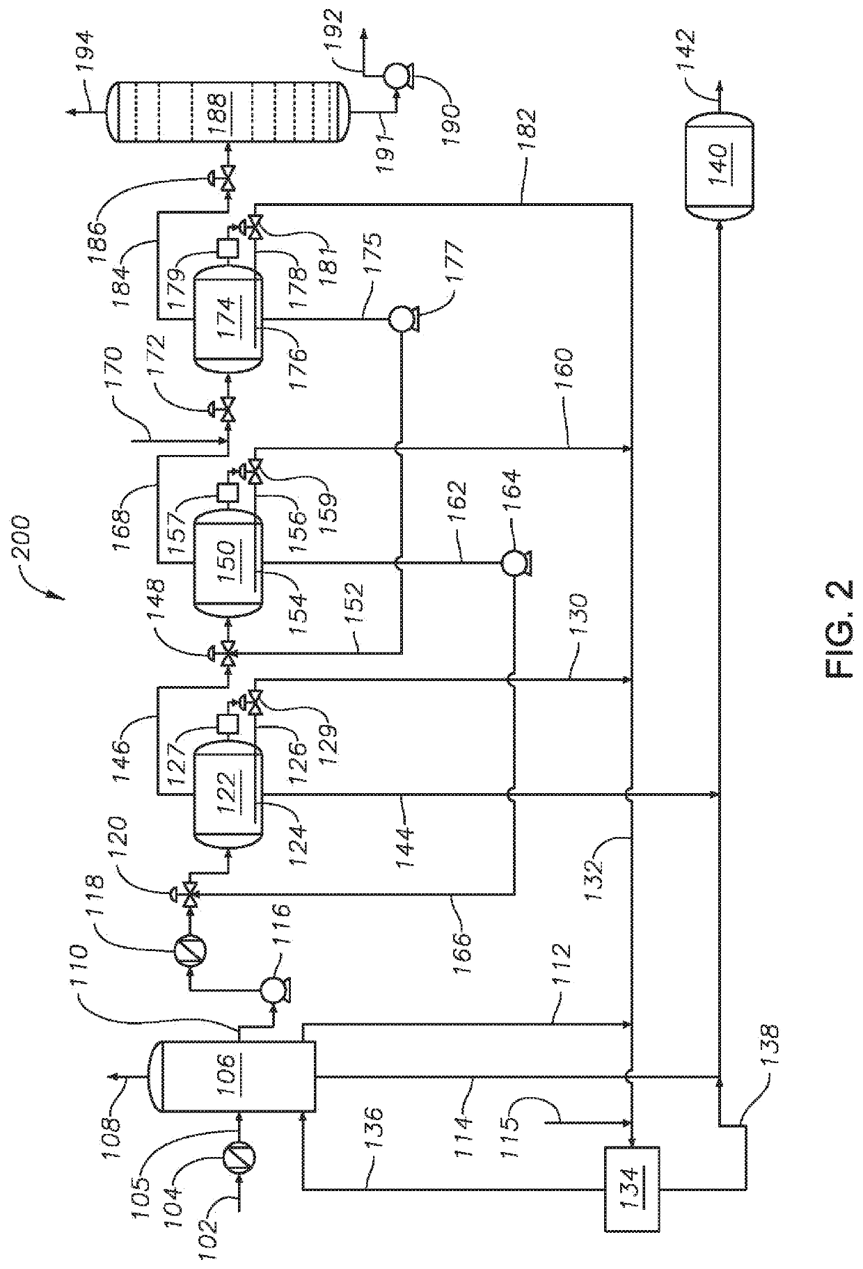
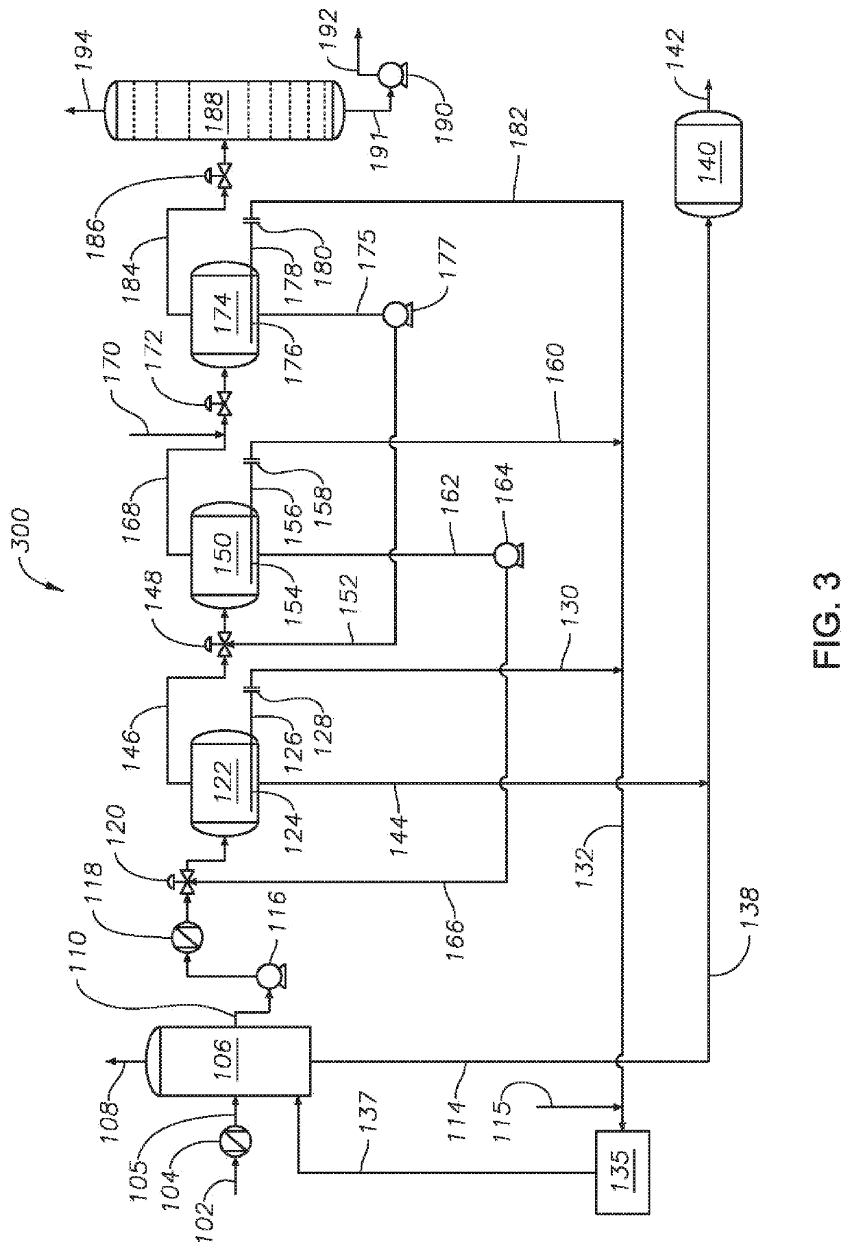
[0041]So that the manner in which the features and advantages of the embodiments of systems and methods of gas oil separation plants for rag layer treatment, as well as others, which will become apparent, may be understood in more detail, a more particular description of the embodiments of the present disclosure briefly summarized previously may be had by reference to the embodiments thereof, which are illustrated in the appended drawings, which form a part of this specification. It is to be noted, however, that the drawings illustrate only various embodiments of the disclosure and are therefore not to be considered limiting of the present disclosure's scope, as it may include other effective embodiments as well.

[0042]For purposes of the present disclosure, tight emulsion crude oil includes emulsions that occur in medium to heavy crude oils with American Petroleum Institute (API) numbers less than about 29. Crude oil specific gravity, along with API numbers, can be used as a measure...


PUM

PropertyMeasurementUnit
pressureaaaaaaaaaa
temperatureaaaaaaaaaa
true vapor pressureaaaaaaaaaa

Abstract

Systems and methods for treating a rag layer in a gas oil separation plant. The method includes withdrawing the rag layer from a vessel proximate an oil water interface, conveying the rag layer to a separation device, and recycling separated oil from the separation device back to the gas oil separation plant process.

Description

PRIORITY[0001]This application is a continuation-in-part application of U.S. patent application Ser. No. 16 / 680,178, filed on Nov. 11, 2019, which itself is a divisional application of U.S. patent application Ser. No. 15 / 866,100, filed Jan. 9, 2018, and issued as U.S. Pat. No. 10,513,663 on Dec. 24, 2019, the entire disclosures of which are incorporated here by reference.BACKGROUNDField[0002]The present disclosure relates to gas oil separation plant (GOSP) technology. In particular, the disclosure relates to the automated, in addition to or alternative to continuous, removal and treatment of the interface layer (rag layer) between oil and water in separation vessels for oil-water emulsions.Description of the Related Art[0003]In general, a GOSP is a continuous separation process used to refine crude oil, which includes a high pressure production trap (HPPT), a low pressure production trap (LPPT), a low pressure degassing tank (LPDT), a dehydrator unit, first and second stage desaltin...

Claims


Application Information

Patent Timeline
Patent Type & Authority Applications(United States)
IPC IPC(8): C10G33/02B01D17/04B03C11/00C10G33/08B01D17/06C02F1/40C10G32/02C02F1/463
CPCB03C11/00B01D17/06B01D17/045C10G32/02C02F1/463C10G33/02B03C2201/02C02F1/40C10G33/08B01D17/12B01D17/085B01D17/042C02F1/44C02F1/385C02F1/04B01D17/0217
Inventor SOLIMAN, MOHAMEDALANAZI, KHALIDSALU, SAMUSIDEEN ADEWALEAL-ZAHRANI, TALAL
Owner SAUDI ARABIAN OIL CO
Why Eureka
Try Eureka