

Retro-reflective interferometer
a technology of retroreflection and interferometer, which is applied in the field of laser interferometer systems and devices, can solve the problems of reducing the reliability of the detector apparatus, affecting the accuracy of the detection apparatus, so as to achieve accurate and efficient detection and measurement of vibrations
- Summary
- Abstract
- Description
- Claims
- Application Information
AI Technical Summary
Benefits of technology
Problems solved by technology
Method used
Image

Examples
example 1
nt of Displacement Using a Microscope
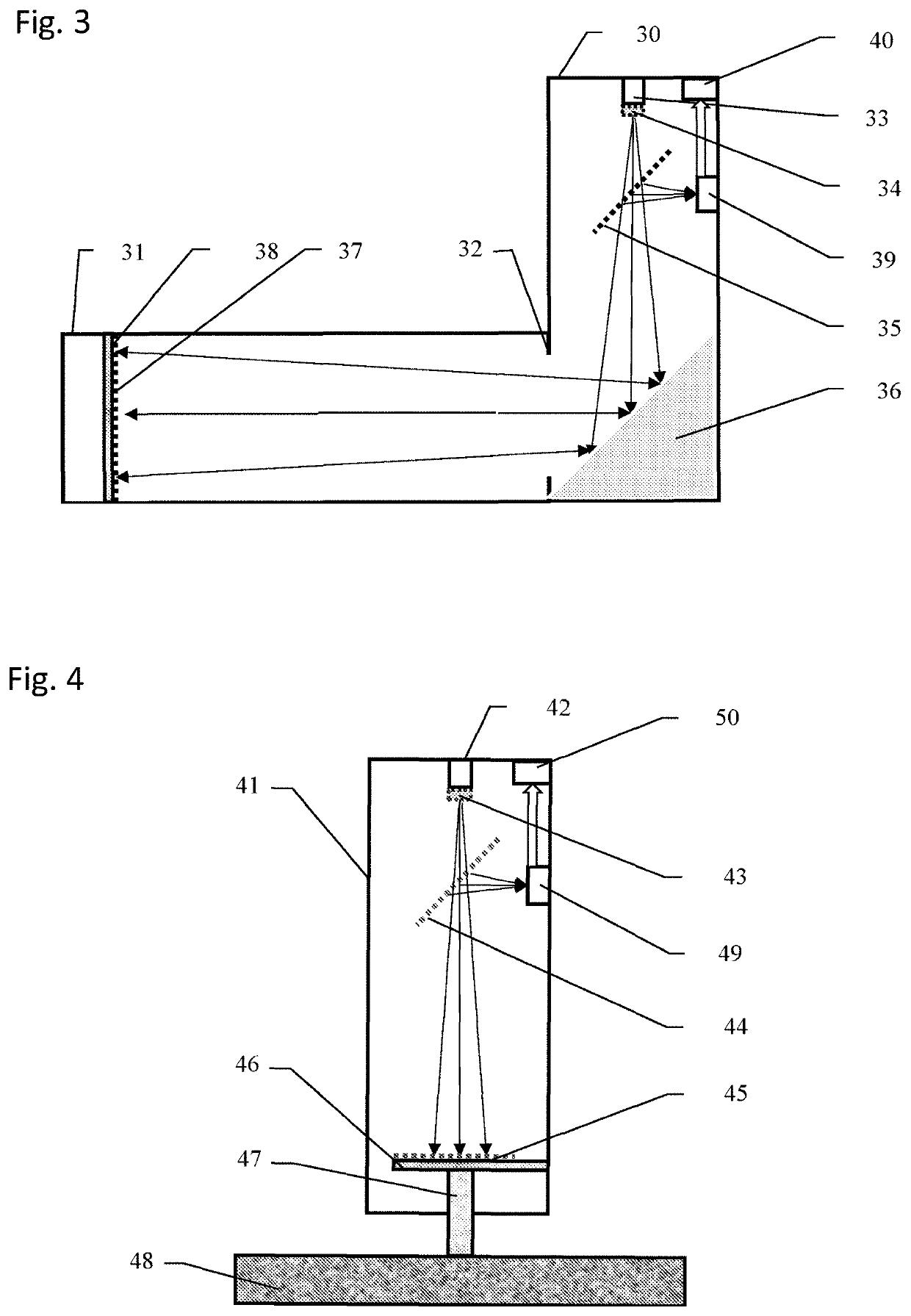
[0364]The following test of the retro-reflective laser seismometer was carried out using a microscope. The device was in the form of a pipe, as detailed above in the FIG. 4.
[0365]Measurement of Displacement Resolution.[0366]The retro-reflective laser seismometer in form of pipe with length of 1260 mm and 50 mm diameter was mounted horizontally[0367]A microscope tube was attached to the cantilever 46 (see FIG. 4) of the seismometer and displaced in horizontal direction with accuracy of 2 μm.[0368]The interference fringes displacement was recorded by the Basler acA3800-14 um USB 3.0 camera with the ON Semiconductor MT9J003 CMOS sensor that delivers 14 frames per second at 10 MP resolution (without additional optics)[0369]During the 50 μm displacement of the microscope tube the interference fringes were displaced by 2500 pixels in the CMOS sensor plane[0370]Therefore, the displacement resolution was:[0371]R=50 μm / 2500 pixels=0.02 μm or 20 nm
example 2
nt of Frequencies Using a Shake Table
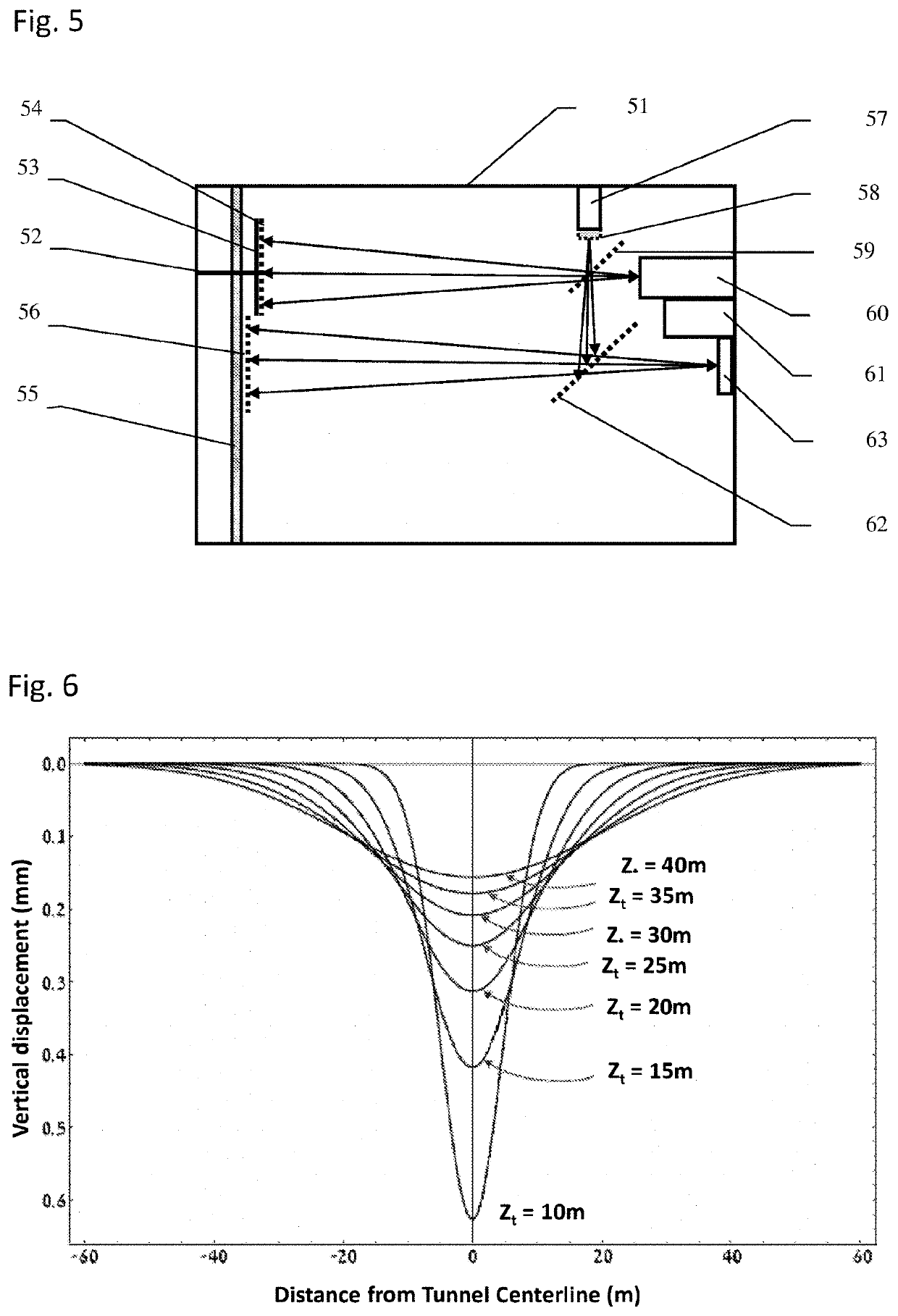
[0372]The following test of the retro-reflective laser seismometer was carried out using the Quanser Shake Table II.
[0373]The seismometer was in the form of the pipes with general length of 1260 mm and 50 mm diameter, as detailed above in the FIG. 3.
[0374]Measurement of Vibration Frequencies[0375]The movable pipe of 1100 mm length (movable unit) of the retro-reflective laser seismometer was mounted on the Quanser Shake Table II at φ=0.048 rad angle to the shake table horizontal surface. The table had horizontal movement along the seismometer pipe[0376]The transceiver unit (stationary portion in the form of a pipe) of the seismometer was fixed to an affixed stand next to the shake table.[0377]Frequencies f of the sine vibrations were measured at 0.5 Hz, 1 Hz and 3 Hz of the shake table vibrations with amplitudes A=0.05 mm, 0.1 mm, 0.2 mm, 0.4 mm, 0.8 mm, 1.6 mm and 3.2 mm. The results at the 0.05 mm amplitude are shown in FIG. 9.
[0378]Based on the...
PUM
 Abstract
Description
Claims
Application Information