Magnetic field sensors, methods of detecting a magnetic field, and related magnetically responsive light propagating components and optical devices

a magnetic field and sensor technology, applied in the field of magnetic field sensors, can solve the problems of low precision, high coupling and propagation loss of fibers, and relatively expensive magnetic field sensing systems, and achieve the effect of effective zero magnetic momentum, enhanced magnetic effect of dopant in host material, and high verdet constan

Active Publication Date: 2020-11-05
UNIV OF SOUTHAMPTON
View PDF9 Cites 2 Cited by
  • Summary
  • Abstract
  • Description
  • Claims
  • Application Information

AI Technical Summary

Benefits of technology

[0030]It is thought that this unexpected behavior can be explained because, in low concentrations, the gadolinium atoms are uniformly dispersed in the host material (e.g. the amorphous silica network), whereas at high concentrations the gadolinium atoms cluster together into a separate material phase. This phase separation that results from a high concentration of gadolinium dopant is shown in FIG. 3, which is a transmission electron microscope (TEM) image of gadolinium doped silica glass at high concentrations (Di Martino, Journal of Non-Crystalline Solids, Volume 354, Issue 32, 15 Aug. 2008, Page 3817) in which the gadolinium clusters or grains in the silica glass host are clearly visible. Gadolinium atoms residing in proximal positions in clusters (as opposed to dispersed locations) will have magnetic momentum pointing in opposite directions, resulting in an overall effectively zero magnetic momentum for the clusters with the magnetic effect of many of the dopant atoms being shielded. The magnetic momentum for the bulk material will then be the sum of only the gadolinium atoms whose magnetic momentum is not compensated by a neighboring gadolinium atom pointing in opposite direction—i.e. only gadolinium atoms which are not shielded.
[0031]In contrast, the low concentration of gadolinium in accordance with the present disclosure avoids phase separation that would result in the above detrimental effect for the Verdet constant. Further, the atomic spin of Gd is the strongest atomic spin in the table of elements and so, with the absence of clustering for low concentration Gd dopants, the magnetic effect of the dopant in the host material is further enhanced. The high Verdet constant of low concentration gadolinium doped bulk materials runs contrary to the previous expected behavior of rare-earth dopants, as it was expected that higher concentrations of rare earth dopants would lead to higher Verdet constants. Indeed, it has been surprisingly discovered that, to achieve a high Verdet constant the concentration of gadolinium may be less than 1% by weight (above which clustering tends to act against a high Verdet constant being achieved), and indeed, a concentration of gadolinium of less than 0.15% by weight may be desirable.
[0032]Thus, by using Gadolinium as a low concentration diffuse (non-clustered) dopant, a high Verdet constant can surprisingly be obtained in an easy-to-manufacture simple silica-based optical or fiber component, without having to rely on expensive-to-manufacture and handle rare earth crystals and bespoke fibers. The component can be easily deployed in an amorphous silica doped network material and can be easily fiberized and handled and spliced with low losses to enable a compact and cheap fiber-based magnetic field sensor to be provided.
[0033]A high Verdet constant is advantageous for magnetic field sensors, as it enables a shorter amount of the magnetically responsive light propagating component to be used, and also may allow for a less complex structure of the magnetic field sensor. This is because fewer, if any, turns of the magnetically responsive light propagating component will be required to achieve the same sensitivity delivered by a pure silica fiber-based sensor.

Problems solved by technology

Yet, these kinds of sensor designs require relatively complex fabrication and thus result in a relatively expensive magnetic field sensing system, and are in particular not suitable for monitoring a magnetic field over a wide area.
This results in large amounts of silica fiber, as much as hundreds of meters, being needed to provide the required magnetic field sensitivity, resulting in a bulky sensor system.
However, the high concentration of the terbium dopant creates a fiber that is difficult to work with as it requires special handling (for example, the fiber is difficult to splice due to a significantly different softening point compared to conventional silica fibers), is expensive to produce, and also causes the fiber to have high coupling and propagation losses, making use of these terbium-doped fibers impractical for use in fiber-based magnetic field sensor systems.

Method used


Image

  • Magnetic field sensors, methods of detecting a magnetic field, and related magnetically responsive light propagating components and optical devices
  • Magnetic field sensors, methods of detecting a magnetic field, and related magnetically responsive light propagating components and optical devices

Examples


example 1

[0066]A sol gel cylinder was tapered on a drawing tower and then inserted in a fluorosilicate tube with a suitable inner to outer diameter ratio before being pulled into a fiber using the rod in tube technique. The fiber was doped with 0.15% by weight of gadolinium.

example 2

[0067]A phosphosilicate soot was deposited inside a high grade silica tube by the modified chemical vapor deposition (MCVD) and then doped with gadolinium ions by solution doping. After consolidation and collapse, the preform was pulled into a fiber with a dopant of 0.15% by weight of gadolinium.

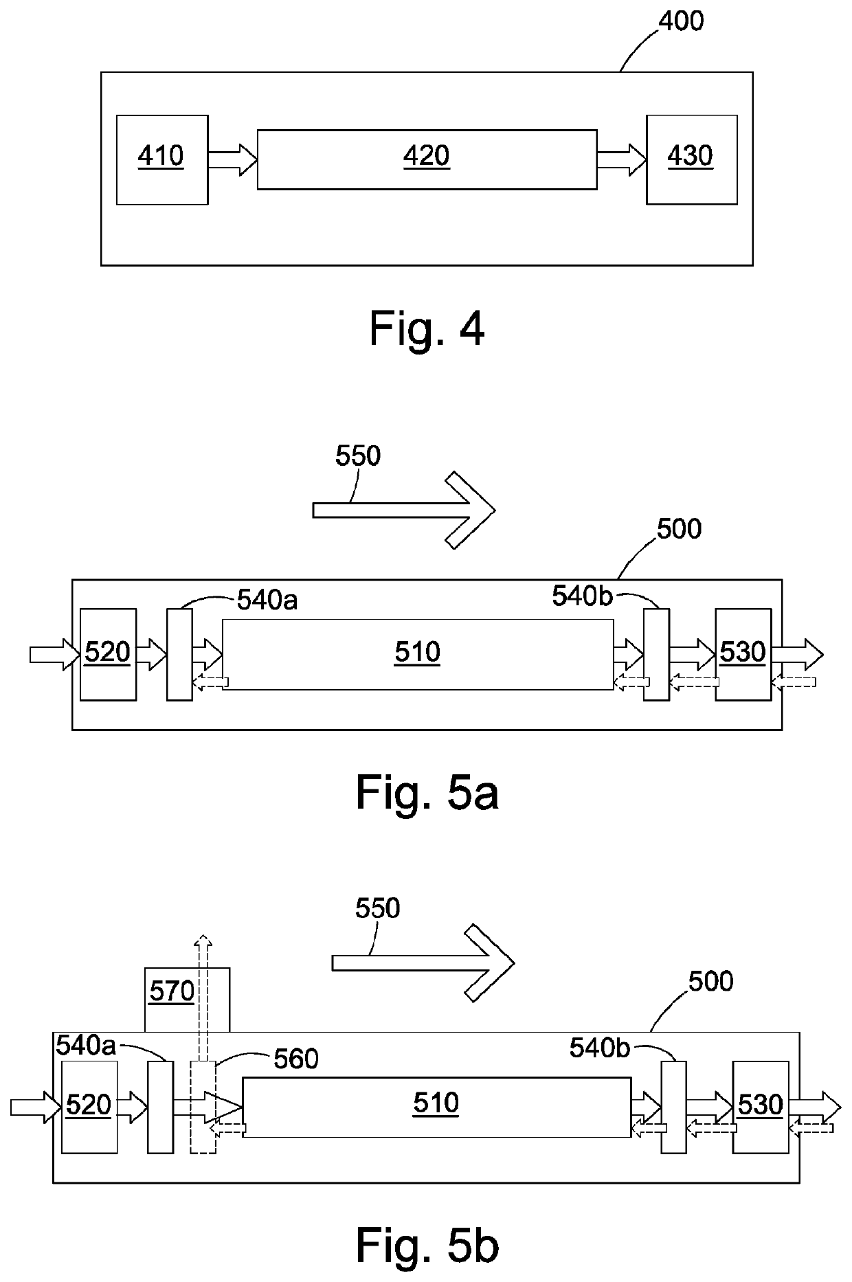
[0068]Both fibers from the above examples were tested by arranging them as the magnetically responsive light propagating component 420 in a magnetic field sensor 400 as described above. A tunable 1550 nm fiberized laser source was used as the linearly polarized light source 410 and a balanced detector was used as the detector 430. Light from the tunable laser source was launched into a polarizer before being split by a polarization maintaining coupler, as described above in relation to the balanced detector implementation. One of the arms of the coupler constituted the reference and was directly connected to a port of a balanced detector. The other arm was spliced to the fiber under test whi...


PUM

PropertyMeasurementUnit
Verdet constantaaaaaaaaaa
lengthaaaaaaaaaa
sizeaaaaaaaaaa

Abstract

A magnetic field sensor comprises a magnetically responsive light propagating component configured to cause a polarization of light propagating inside the component to be rotated in response to an applied magnetic field, wherein the magnetically responsive light propagating component is formed of a bulk material doped with a dopant, the dopant including at least gadolinium, the dopant concentration being at a sufficiently low concentration such that the dopant is uniformly dispersed in the bulk material to provide a high Verdet constant. The magnetic field sensor also comprises a detector, and a polarization-maintaining light input device to couple the light into the magnetically responsive light propagating component. The detector is configured to measure a property of light output from the magnetically responsive light propagating component to determine a change in polarization of the light, the change caused by the presence of a magnetic field.

Description

CROSS-REFERENCES TO RELATED APPLICATIONS[0001]This application claims priority to and is a continuation of International Patent Application No. PCT / GB2018 / 053403, filed Nov. 26, 2018; which claims priority from GB Patent Application No. 1719576.9, filed Nov. 24, 2017, the entire contents of which are hereby incorporated by reference in their entirety for all purposes.TECHNICAL FIELD[0002]The application relates to the technical field of magnetic field sensors. In particular, the application relates to magnetic field sensors incorporating magnetically responsive light propagating components formed to be usable as Faraday rotators, in particular in fiber form. The application also relates to other optical apparatus incorporating the magnetically responsive light propagating components.BACKGROUND OF THE INVENTION[0003]Magnetic field sensors have found numerous applications in a variety of fields including navigation, current sensing, space and geophysics. Many magnetic field sensors re...

Claims


Application Information

Patent Timeline
Patent Type & Authority Applications(United States)
IPC IPC(8): G01R33/032G02F1/01G02F1/00G02F1/095
CPCG02F1/0955G02F1/0036G01R33/0322G02F1/0136G02F2202/06G02F1/093
Inventor ISMAEEL, RANDMASOUDI, ALIBERESNA, MARTYNASBRAMBILLA, GILBERTO
Owner UNIV OF SOUTHAMPTON
Why Eureka
Try Eureka