Organic electroluminescent element

a technology of electroluminescent elements and organic compounds, applied in the field of organic electroluminescent elements, can solve the problems of difficult commercialization, difficult to display deep blue, and and achieve the effects of improving efficiency, color characteristics and lifetime, and preventing deterioration of color characteristics

Pending Publication Date: 2021-02-25
MATERIAL SCIENCES CORPORATION
View PDF3 Cites 3 Cited by
  • Summary
  • Abstract
  • Description
  • Claims
  • Application Information

AI Technical Summary

Benefits of technology

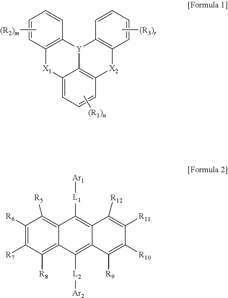
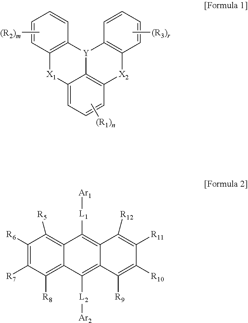
[0016]n is an integer ranging from 0 to 3;
[0017]m and r are the same or different and are each independently an integer ranging from 0 to 4;
[0052]The present disclosure provides an organic electroluminescent element that may exhibit improved efficiency, color characteristics and lifetime.
[0053]In particular, the present disclosure provides an organic electroluminescent element, which is prevented from deterioration in color characteristics and has characteristics such as long lifetimes, as a result of using a host material having a specific structural formula despite having high polarity.
[0054]The present disclosure is directed to an organic electroluminescent element including: a first electrode; a second electrode; and at least one organic layer disposed between the first electrode and the second electrode, wherein the organic layer includes a light-emitting layer, wherein the light-emitting layer includes a compound represented by the following Formula 1 and a compound represented by the following Formula 2:
[0066]The organic electroluminescent element according to the present disclosure is characterized by having a long lifetime effect while maintaining the excellent color purity of the organic electroluminescent element, as a result of introducing a host / dopant system using novel organic compounds.

Problems solved by technology

However, the full-width at half maximum of these dopants is wide at 40 nm, making it difficult to display deep blue.
In addition, optical loss occurs even when a certain wavelength region is amplified through optical resonance in a top-emission element.
Although these dopants exhibit high efficiency and realize excellent color, they remain difficult to commercialize due to their low lifetime.

Method used


Image

  • Organic electroluminescent element
  • Organic electroluminescent element
  • Organic electroluminescent element

Examples


synthesis example 1-1

[0097]

[0098]8.9 g (20 mmol) of starting material was dissolved in tert-butylbenzene (250 ml), and then the solution was cooled to 0° C. Under a nitrogen atmosphere, 24.7 ml (42 mmol) of 1.7 M tert-butyllithium solution (in pentane) was added thereto, followed by stirring at 60° C. for 2 hours.

[0099]Thereafter, the reaction solution was cooled again to 0° C. and 4.0 ml (42 mmol) of BBr3 was added thereto, followed by stirring at room temperature for 0.5 hours. Then, the reaction solution was cooled again to 0° C. and 7.3 ml (42 mmol) of N,N-diisopropylethylamine was added thereto, followed by stirring at 60° C. for 2 hours.

[0100]The reaction solution was cooled slowly to room temperature, and the organic layer was extracted with ethyl acetate and water. The solvent was removed from the extracted organic layer, followed by purification by silica gel column chromatography (DCM / hexane). Then, recrystallization from a DCM / acetone mixture solvent afforded 1.7 g of compound 1-1 in a yield ...

synthesis example 1-2

[0102]

[0103]2.16 g of compound 1-3 was obtained in a yield of 23.0% by performing an experiment in the same manner as in Synthesis Example 1-1, except that 9.9 g (20 mmol) of starting material 1-3 was used instead of starting material 1-1.

[0104]MS (MALDI-TOF) m / z: 470 [M]+

synthesis example 1-3

[0105]

[0106]2.3 g of compound 1-5 was obtained in a yield of 23.2% by performing an experiment in the same manner as in Synthesis Example 1-1, except that 10.6 g (20 mmol) of starting material 1-5 was used instead of starting material 1-1.

[0107]MS (MALDI-TOF) m / z: 502 [M]+


PUM

PropertyMeasurementUnit
full-width at half maximumaaaaaaaaaa
temperatureaaaaaaaaaa
current densityaaaaaaaaaa

Abstract

The present disclosure relates to an organic electroluminescent element, and more particularly to an organic electroluminescent element including a novel boron-based organic compound and anthracene-based organic compound in one or more organic layers included in the organic electroluminescent element. The present disclosure may provide an organic electroluminescent element, which is prevented from deterioration in color characteristics and has characteristics such as long lifetimes, as a result of using a host material having a specific structural formula despite having high polarity.

Description

TECHNICAL FIELD[0001]The present disclosure relates to an organic electroluminescent element, and more particularly to an organic electroluminescent element including a novel boron-based organic compound and anthracene-based organic compound in one or more organic layers included in the organic electroluminescent element.BACKGROUND ART[0002]An organic electroluminescent element has a structure including a cathode (electron injection electrode), an anode (hole injection electrode) and one or more organic layers provided between the two electrodes.[0003]The organic electroluminescent element includes a hole injection layer (HIL), a hole transport layer (HTL), a light-emitting layer (EML), an electron transport layer (ETL) and an electron injection layer (EIL), stacked in that order from the anode, and may further include an electron-blocking layer (EBL) and a hole-blocking layer (HBL) over and under the light-emitting layer, respectively, in order to increase the efficiency of the lig...

Claims


Application Information

Patent Timeline
Patent Type & Authority Applications(United States)
IPC IPC(8): C07F5/02H01L51/00
CPCC07F5/027H01L51/0072H01L51/5056H01L51/0073H01L51/0074H01L51/008H10K85/626H10K85/615H10K85/322H10K85/6576H10K85/6574H10K50/11H10K85/6572H10K50/15H10K50/16H10K50/18H10K50/171H10K85/658
Inventor KIM, SUNG HOONJEONG, JAE HOKANG, HYUN BINKIM, JIN-SUNGKWAK, TAE-HO
Owner MATERIAL SCIENCES CORPORATION
Why Eureka
Try Eureka