Flexible laminated board and multilayer circuit board

a multi-layer circuit board and laminated sheet technology, applied in the direction of metallic pattern materials, layered product treatment, synthetic resin layered products, etc., can solve the problem of more conduction failures between the layers of each multi-layer circuit board, and achieve the effect of reducing conduction failures and small dimensional change ra

Pending Publication Date: 2021-05-20
UBE NITTO KASEI CO LTD
View PDF5 Cites 1 Cited by
  • Summary
  • Abstract
  • Description
  • Claims
  • Application Information

AI Technical Summary

Benefits of technology

[0017]The present invention succeeds in providing a flexible laminated sheet having a small dimensional change rate. Further, the present invention succeeds in reducing conduction failures between the layers of a multilayer circuit board.

Problems solved by technology

When manufacturing multilayer circuit boards in each of which pattern films are used that each include an insulation film formed of a different liquid crystal polymer, conduction failures between the layers of each multilayer circuit board occurs more often when using an insulation film formed of a type II liquid crystal polymer than when using an insulation film formed of a type I liquid crystal polymer.

Method used


Image

  • Flexible laminated board and multilayer circuit board
  • Flexible laminated board and multilayer circuit board

Examples


first embodiment

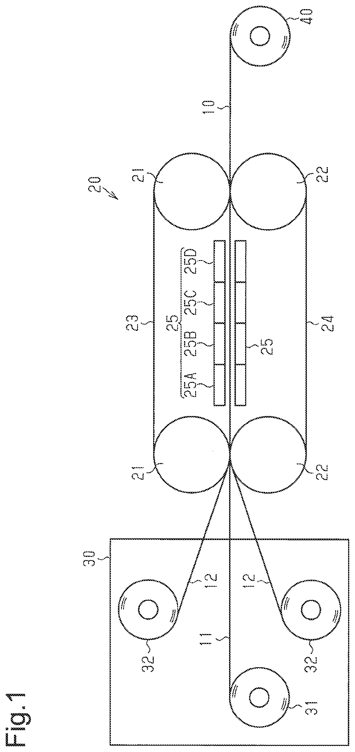
[0020]One embodiment of a flexible laminated sheet manufacturing method of the present invention will now be described in detail with reference to FIG. 1.

[0021]A method for manufacturing a flexible laminated sheet 10 of the present embodiment includes a thermocompression bonding step of continuously thermocompression-bonding a metal foil 12 onto each surface of an insulation film 11. The flexible laminated sheet 10 is manufactured through the thermocompression bonding step.

[0022]First, the insulation film 11 and the metal foils 12 used for manufacturing the flexible laminated sheet 10 will be described.

[0023]The insulation film 11 forms an insulation layer of the flexible laminated sheet 10. The insulation film 11 is formed of a liquid crystal polymer having a melting point in excess of 250° C. Examples of such a liquid crystal polymer include a liquid crystal polymer containing as constituent units ethylene terephthalate and para-hydroxybenzoic acid, a liquid crystal polymer contai...

second embodiment

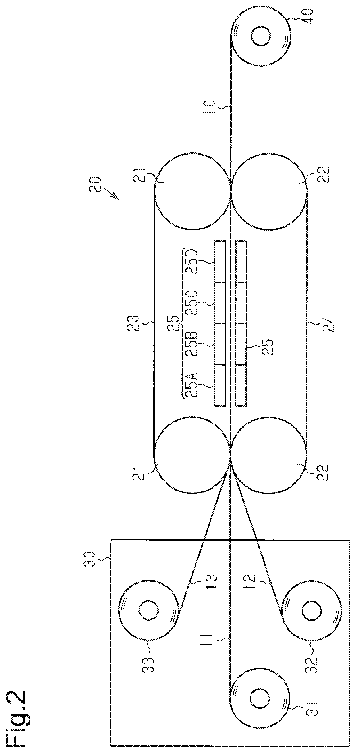
[0071]One embodiment of a laminated sheet manufacturing method of the present invention will now be described in detail.

[0072]A method for manufacturing a laminated sheet of the present embodiment includes a drying step of drying an insulation film and a thermocompression bonding step of thermocompression-bonding a metal foil onto the insulation film after the drying step. The laminated sheet is manufactured through the drying step and the thermocompression bonding step.

[0073]First, the insulation film and the metal foil used for manufacturing the laminated sheet will be described.

[0074]The insulation film forms an insulation layer of the laminated sheet. An insulation film formed of a polymer of 6-hydroxy-2-naphthoic acid and 4-hydroxybenzoic acid (hereinafter referred to as type II liquid crystal polymer) is used as the insulation film. The melting point of the type II liquid crystal polymer is preferably in the range from 280° C. to 360° C. and more preferably in the range from 3...

example 206

[0105]An insulation film cut out to a predetermined size was put into a drying device, and the insulation film was dried by applying to the insulation film a hot air having a predetermined temperature (drying step). Subsequently, a metal foil was placed on each surface of the dried insulation film, and the insulation film and the metal foils were thermocompression-bonded together by a heat press (thermocompression bonding step).

[0106]Evaluation of Dynamic Thermal Deformation Amount

[0107]The metal layers of both surfaces of the laminated sheet obtained in each of examples 201 to 206 and comparative examples 201 to 206 were removed through an etching process with a ferric chloride solution. A sample of 10 mm length×5 mm width was cut out from the remaining insulation film (insulation layer) and set to a dynamic viscoelasticity measurement device (made by UBM, Rheogel-E4000). The dynamic viscoelasticity measurement device set the dynamic load to 15 g and the frequency to 1 Hz in a dyna...


PUM

PropertyMeasurementUnit
temperatureaaaaaaaaaa

Abstract

A flexible laminated sheet manufacturing method includes thermocompression-bonding an insulation film formed of a liquid crystal polymer onto a metal foil between endless belts to form a flexible laminated sheet. The thermocompression bonding includes heating the flexible laminated sheet so that the maximum temperature of the sheet is in the range from a temperature that is 45° C. lower than the melting point of the liquid crystal polymer to a temperature that is 5° C. lower than the melting point. The thermocompression bonding also includes slowly cooling the flexible laminated sheet so that an exit temperature, which is a temperature of the sheet when transferred out of the endless belts, is in the range from a temperature that is 235° C. lower than the melting point of the liquid crystal polymer to a temperature that is 100° C. lower than the melting point.

Description

CROSS-REFERENCE TO RELATED APPLICATIONS[0001]This application is a divisional application of co-pending U.S. application Ser. No. 15 / 541,630 filed on Jul. 5, 2017 entitled “Flexible Laminated Board and Multilayer Circuit Board,” which is a US 371 application from PCT / JP2016 / 050709 filed Jan. 12, 2016, which claims priority to Japanese Patent Application No. 2015-004337 filed Jan. 13, 2015, and to Japanese Patent Application No. 2015-004338 filed Jan. 13, 2015, the technical disclosures of which are hereby incorporated herein by reference.TECHNICAL FIELD[0002]The present invention relates to a flexible laminated sheet and a multilayer circuit board.BACKGROUND ART[0003]A flexible laminated sheet in which an insulation layer and a metal layer are bonded together is used as, for example, a material for manufacturing a flexible printed wiring board. A flexible laminated sheet that uses a liquid crystal polymer, which is a low-dielectric material, in an insulation layer is drawing attenti...

Claims


Application Information

Patent Timeline
Patent Type & Authority Applications(United States)
IPC IPC(8): H05K1/03B32B15/08B32B15/088B32B37/10H05K3/02B32B3/08B32B15/20B32B7/04B32B15/098B32B7/06B32B27/36B32B27/42B32B15/18B32B27/28B32B15/09B32B37/06B32B37/08H05K1/09H05K1/11H05K3/46
CPCH05K1/0393H05K3/067B32B15/088B32B37/1027H05K3/022B32B3/08B32B15/20B32B7/04B32B15/098B32B7/06B32B27/36B32B27/42B32B15/18B32B27/28B32B27/283B32B27/281B32B15/09B32B37/06B32B37/08B32B37/10H05K1/09H05K1/115H05K3/4655B32B2309/02B32B2309/04B32B15/08B32B2457/20H05K3/227H05K2201/0191H05K2201/068H05K2203/1545H05K2203/1194B32B2250/02B32B2250/03B32B2250/40B32B2307/30B32B2307/302B32B2307/306B32B2307/50B32B2307/538B32B2307/546B32B2307/732B32B2307/734B32B2307/748B32B2405/00B32B2457/08H05K2201/0141B32B7/02H05K1/03B32B2309/12B32B2305/55B32B2307/206B29C43/48B29C48/9145B65G15/12H05K2203/066
Inventor TACHIBANA, EISUKESUZUKI, TAROTOTANI, MAKOTOKONDOH, KOUJIMIYAGAWA, EIJIROUKASAHARA, JUNYAARIMA, TAKAO
Owner UBE NITTO KASEI CO LTD
Why Eureka
Try Eureka