Wound Dressings and Systems with Low-Flow Therapeutic Gas Sources for Topical Wound Therapy and Related Methods

Pending Publication Date: 2021-08-05
KCI LICENSING INC
View PDF3 Cites 1 Cited by
  • Summary
  • Abstract
  • Description
  • Claims
  • Application Information

AI Technical Summary

Benefits of technology

[0007]The present dressings, systems, and/or methods can provide greater efficacy and/or accuracy in the supply and/or delivery of the topical application of therapeutic gas, such as, for example, oxygen, to target tissue. Oxygen, in certain concentrations, can exhibit an

Problems solved by technology

Although these traditional oxygen-based therapies can supply high-purity oxygen (e.g., via electrolysis of atmospheric water vapor) to wound dressings, these therapies may require days of operation before the oxygen concentration at the target tissue is greater than 80 percent at least because of ineffective distribution and/or retention of oxygen within the dressing.
Ineffecti

Method used


Image

  • Wound Dressings and Systems with Low-Flow Therapeutic Gas Sources for Topical Wound Therapy and Related Methods
  • Wound Dressings and Systems with Low-Flow Therapeutic Gas Sources for Topical Wound Therapy and Related Methods
  • Wound Dressings and Systems with Low-Flow Therapeutic Gas Sources for Topical Wound Therapy and Related Methods

Examples


example 1

Changes in Oxygen Concentration within a Dressing Comprising the Gas-Occlusive Layer of the Present Disclosure

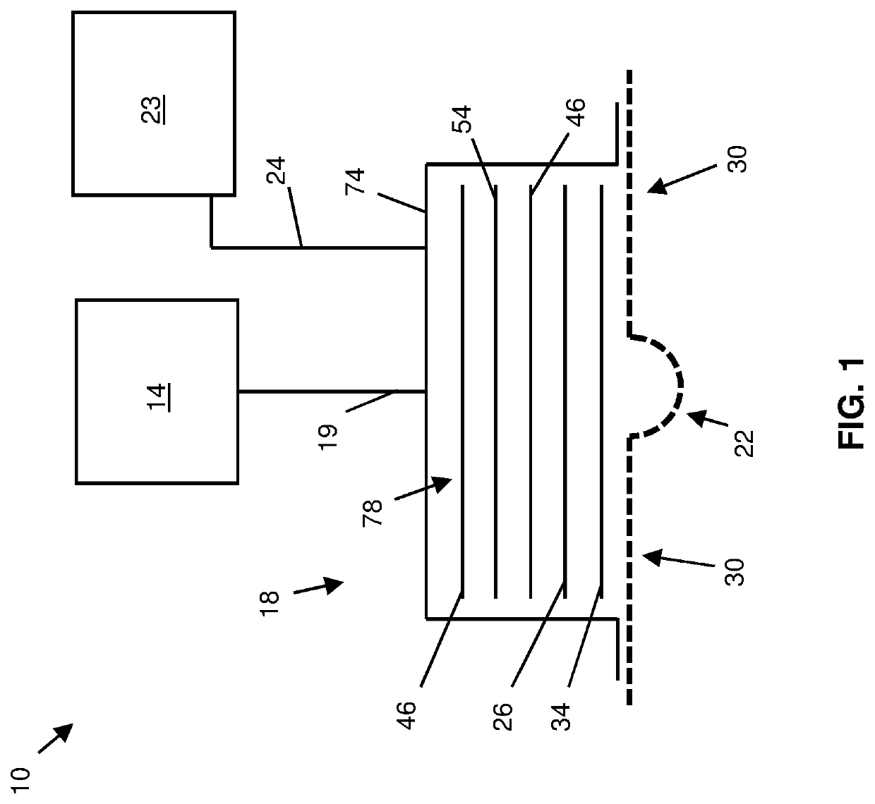
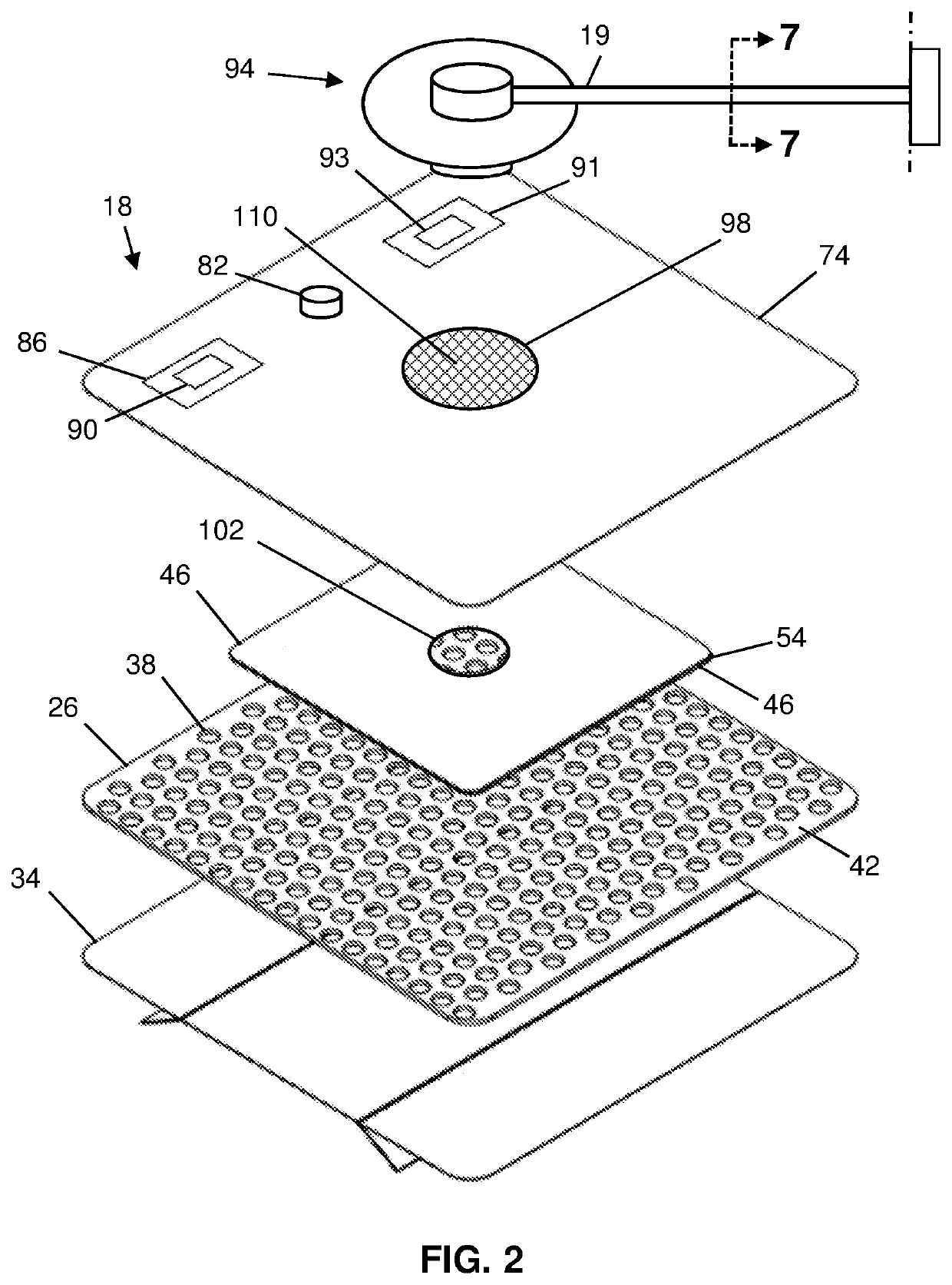
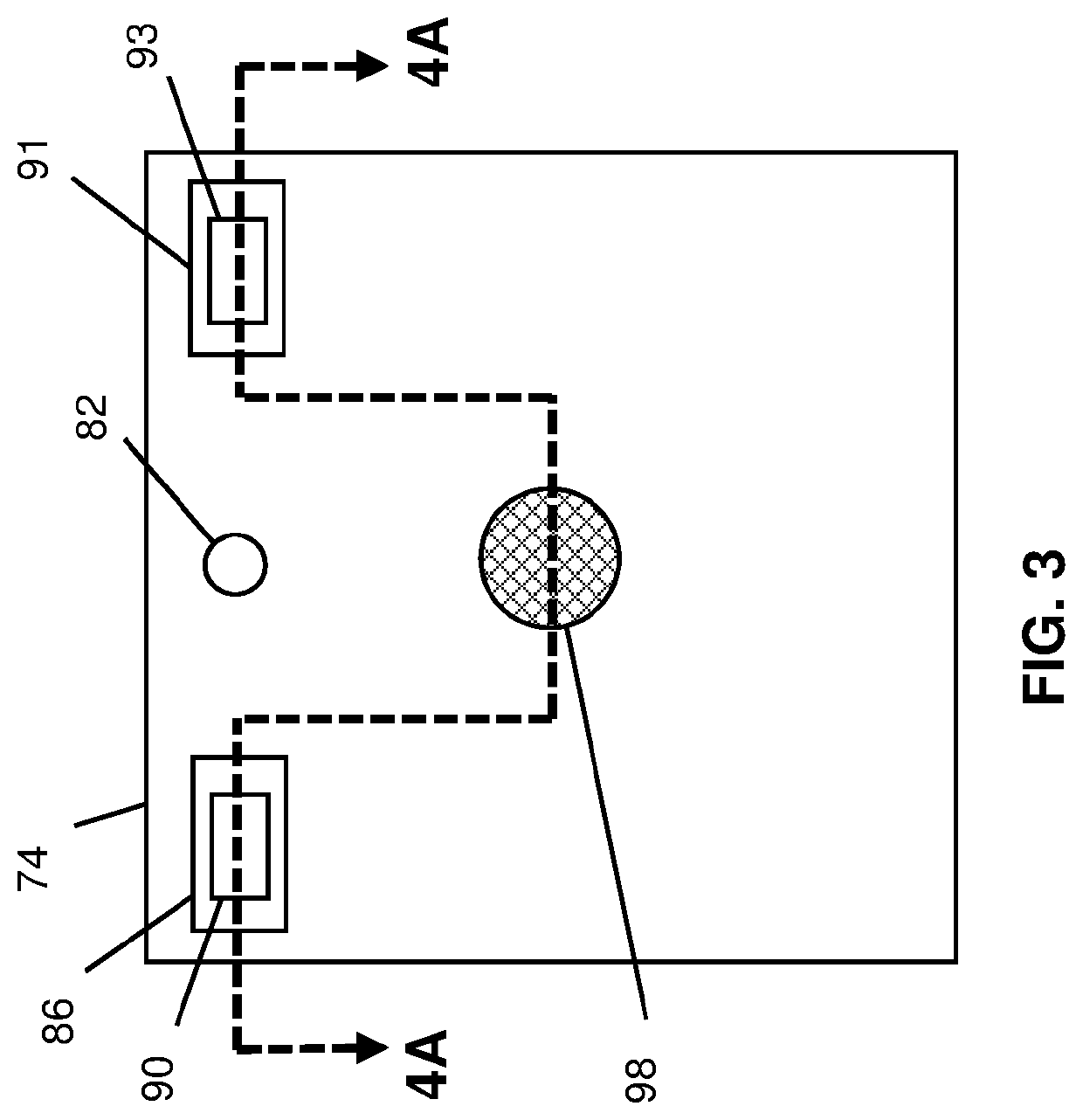
[0114]An SO-220 Fast Response Thermocouple Reference Oxygen Sensor, which is commercially available from Apogee Instruments, Inc., of Logan, Utah, USA, was used to evaluate the oxygen concentration within a first 4-inch by 5-inch dressing and a second 4-inch by 5-inch dressing, each having, in the following order, from farthest to closest to tissue (e.g., 22 or 30): an semi-occlusive film comprising a polyurethane adhesive, a super absorbent textile, a manifold comprising an open cell foam, and a patient interface layer comprising a hydrophilic foam. Each dressing also comprised a cannula inserted through the semi-occlusive film and into the manifold to deliver oxygen to the dressing. The second dressing, in contrast to the first dressing, additionally had a gas-occlusive layer (e.g., 74) comprising a polyurethane film coated with a layer of adhesive at least as thick as the...

example 2

Changes in Oxygen Concentration within a Dressing Comprising the Gas-Occlusive Layer of the Present Disclosure Before and after Liquid Instillation

[0116]An SO-220 Fast Response Thermocouple Reference Oxygen Sensor, which is commercially available from Apogee Instruments, Inc., of Logan, Utah, USA, was used to evaluate the levels of oxygen concentration within a 4-inch by 4-inch TIELLE™ Dressing, which is commercially available from Systagenix Wound Management, Limited, of Gargrave, UK (“Systagenix”). The dressing included, in the following order, from farthest to closest to tissue (e.g., 22 or 30): a moisture-permeable polyurethane film with a skin-friendly adhesive, a hydropolymer-based compressed superabsorbent material comprising LIQUALOCK™ Advanced Absorption Technology, which is commercially available from Systagenix, a manifolding assembly (e.g., 83) having a gas occlusive layer (e.g., 74a) adhered to a porous polyethylene manifold (e.g., 46a), the manifolding assembly also ha...


PUM


Abstract

This disclosure includes wound dressings and systems with low-flow, high-concentration therapeutic gas sources for topical wound therapy and related methods. Some dressings, which are configured to be coupled to tissue to facilitate delivery of therapeutic gas to the tissue, comprise a manifold that defines a plurality of gas passageways, the manifold configured to allow communication of therapeutic gas to the tissue; a sorbent material configured to be disposed above or below the manifold and to capture exudate; and a gas-occlusive layer configured to be disposed over the manifold and the sorbent material and coupled to the tissue such that an interior volume containing the manifold and the sorbent material is defined between the gas-occlusive layer and the tissue and the gas-occlusive layer limits escape of therapeutic gas from the interior volume.

Description

CROSS-REFERENCE TO RELATED APPLICATIONS[0001]The application claims the benefit of U.S. Provisional Application No. 62 / 576,487, filed Oct. 24, 2017, the contents of which are incorporated herein in its entirety.BACKGROUND1. Field of Invention[0002]The present invention relates generally to wound dressings, and more specifically, but not by way of limitation, to wound dressings and systems with low-flow therapeutic gas sources for topical wound therapy and related methods.2. Description of Related Art[0003]Clinical studies and practice have shown that topical applications of therapeutic gas, such as, for example, oxygen, can improve wound healing, especially in chronic wounds. Topical applications of therapeutic gas can reduce tissue inflammation and / or improve tissue proliferation (e.g., improve collagen synthesis, growth factor production, angiogenesis, and / or the like).[0004]Traditional oxygen-based therapies can supply oxygen at relatively low-flow rates, such as, for example, be...

Claims


Application Information

Patent Timeline
IPC IPC(8): A61F13/02A61M1/00
CPCA61F13/0216A61F13/022A61F13/0223A61F2013/00255A61M1/94A61M2202/0208A61F13/0209A61M1/00A61F13/00068A61F2013/0017A61M2205/3344A61M35/30A61M2205/3324A61M1/73A61M1/964A61M1/85A61M1/915A61M1/95A61F2013/00268A61M2205/3334
Inventor LONG, JUSTIN ALEXANDERLOCKE, CHRISTOPHER BRIANROBINSON, TIMOTHY MARK
Owner KCI LICENSING INC
Why Eureka
Try Eureka