Optical scanning holography system

a holographic system and optical scanning technology, applied in the field of optical scanning holography system, can solve the problems of complex electro-optical structure, high cost, and high complexity of electro-optical system, and achieve the effects of miniaturizing and lightening, and reducing the complexity of a structur

Pending Publication Date: 2021-11-04
CUBIXEL CO LTD
View PDF4 Cites 0 Cited by
  • Summary
  • Abstract
  • Description
  • Claims
  • Application Information

AI Technical Summary

Benefits of technology

[0038]According to an in-line scanning holography system of the present disclosure, a high-efficiency and high-quality optical scanning holography may be implemented by forming a scan pattern in a single optical path by using a polarization-sensitive lens and also there is an advantage in that the optical scanning holography is resistant to external environment by using a high-stability and low-complexity optical system structure.
[0039]In addition, according to a geometric phase scanning holography system of the present disclosure, a complex hologram of a real object without bi-image noise and background noise may be obtained by using a geometric structure according to polarization without using a complicated modulator for modulating an optical signal, and thus, the geometric phase scanning holography system has a reduced complexity of a structure and may be miniaturized and lightened and may also be applied to mobile devices sensitive to energy consumption.
[0040]In addition, according to a geometric phase in-line scanning holography system according to the present disclosure, the geometric phase in-line scanning holography system has high stability and low complexity by forming a scan pattern in a single optical path by using a polarization-sensitive lens, and a complex hologram of a real object without bi-image noise and background noise may be obtained by using a geometric structure according to polarization even without using a complicated modulator, and thus, a high-efficiency and high-quality optical scanning holography may be implemented.

Problems solved by technology

In addition, a bulky optical system for separating and recombining light is required, and also a complicated electro-optical structure for modulating each of the first and second beams in time and space is required.
Moreover, there is a problem in that the electro-optical system having such a complex structure is very vulnerable to external environmental factors such as vibration is unstable.
However, the acoustic optical modulator is bulky and requires a high-frequency signal generating device in the MHz band and requires high-energy sound wave generation, and thus, power loss is large.
In addition, the electro-optical modulator is not only bulky but also requires a voltage amplifier for generating a high voltage and has a high complexity of the device.
These problems act as the biggest obstacle in practical use of the existing optical scanning hologram.

Method used


Image

  • Optical scanning holography system
  • Optical scanning holography system
  • Optical scanning holography system

Examples


first embodiment

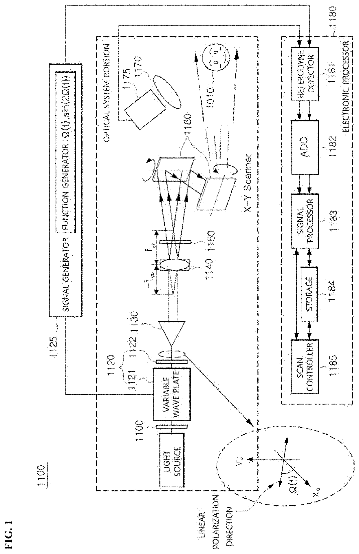
[0066]FIG. 1 is a diagram illustrating an in-line scanning holography system according to the present disclosure.

[0067]As illustrated in FIG. 1, an in-line scanning holography system 1100 according to the first embodiment includes a polarizer 1110, a linear polarization direction converter 1120, a signal generator 1125, a collimator 1130, a polarization-sensitive lens 1140, a polarizer 1150, scanning unit 1160, a light integrator 1170, a first photodetector 1175, and an electronic processor 1180.

[0068]First, a light source generates electromagnetic waves. In an embodiment of the present disclosure, the light source may include various devices such as a laser generator that outputs coherent light, a light emitting diode (LED) lamp with low coherence, and a halogen lamp having a short coherence length.

[0069]The polarizer (linear polarizer) 1110 converts an inputted beam into a linearly polarized beam and provides the linearly polarized beam to the linear polarization direction convert...

second embodiment

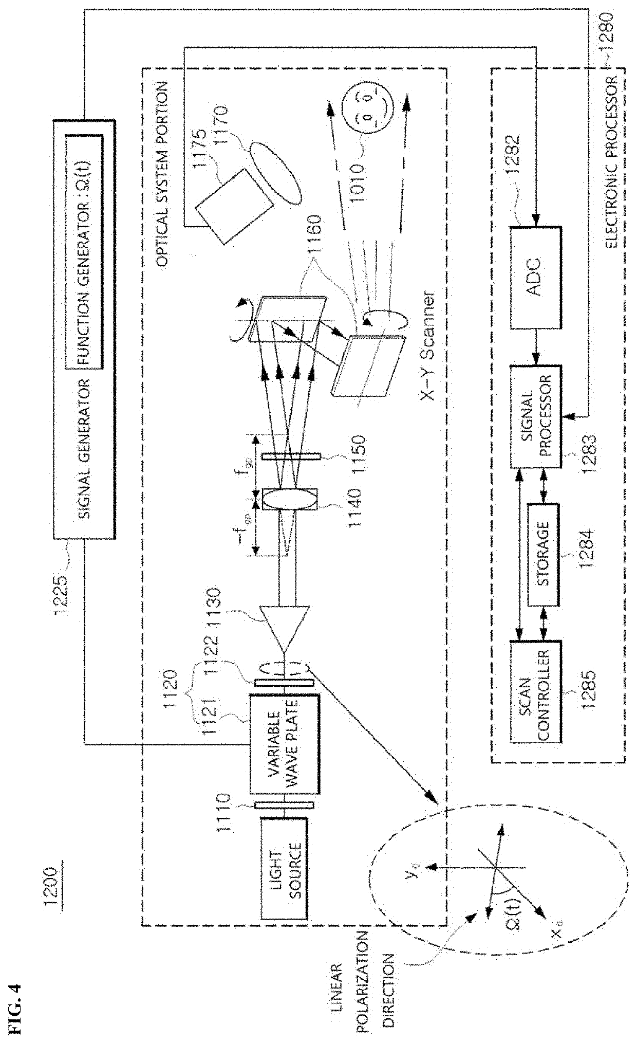
[0107]FIG. 4 is a diagram illustrating the in-line scanning holography system according to the present disclosure.

[0108]As illustrated in FIG. 4, the in-line scanning holography system 1200 according to the second embodiment includes a polarizer 1110, a linear polarization direction converter 1120, a signal generator 1225, a collimator 1130, a polarization-sensitive lens 1140, a polarizer 1150, scanning unit 1160, a light integrator 1170, a first photodetector 1175, and an electronic processor 1280. In FIG. 4, components having the same reference numerals as in the first embodiment of FIG. 1 perform the same operation, and thus, additional description thereon is omitted.

[0109]In FIG. 4, a phase modulation signal generated by the signal generator 1225 corresponds to a phase shift signal whose phase retardation value is discontinuously shifted in the order of (0, π / 2, π) with time, unlike FIG. 1. Accordingly, a function generator of the signal generator 1225 generates a phase shift si...

third embodiment

[0114]FIG. 5 is a diagram illustrating the in-line scanning holography system according to the present disclosure.

[0115]As illustrated in FIG. 5, the in-line scanning holography system 1300 according to the third embodiment includes a polarizer 1110, a linear polarization direction converter 1120, a signal generator 1125, a collimator 1130, a polarization-sensitive lens 1140, a polarizer 1150, a first lens 1355, scanning unit 1160, a light integrator 1170, a first photodetector 1175, and an electronic processor 1180.

[0116]FIG. 5 illustrates that the first lens 1355 is additionally added to the structure according to the first embodiment of FIG. 1, and additional description on the components having the same reference numerals is omitted.

[0117]In FIG. 5, the first lens 1355 is provided between the polarization-sensitive lens 1140 and the scanning unit 1160 to adjust a distance between respective focal points of the first and second spherical waves and acts as an imaging lens for imag...


PUM

PropertyMeasurementUnit
focal lengthaaaaaaaaaa
phaseaaaaaaaaaa
phase retardationaaaaaaaaaa

Abstract

An optical scanning holography system includes a polarization-sensitive lens configured to receive a linearly polarized beam and generate a first spherical wave of right-handed circular polarized light having a negative focal length and a second spherical wave of left-handed circular polarized light having a positive focal length, a first polarizer configured to pass only a beam component therethrough in a predetermined polarization direction among components of the generated first and second spherical waves, a scanning unit configured to scan an object by using an interference beam generated between the first and second spherical waves passing through the first polarizer, and a first photodetector configured to detect a beam reflected from the object.

Description

TECHNICAL FIELD[0001]The present disclosure relates to an optical scanning holography system, and more particularly, to an optical scanning holography system capable of implementing a high-efficiency and high-quality optical scanning holography.BACKGROUND ART[0002]An optical scanning-based object hologram acquisition device of the related art formed a scanning beam pattern by using an interferometric structure that spatially splits coherent light (interferable light) into a first beam and a second beam and then temporally and spatially performs an optical modulation of the first and second beams traveling along each individual optical path on separate optical paths and recombines the beams again.[0003]However, in the related art, a difference between separated two optical paths has to be shorter than a coherence length of coherence light in order to form a scan pattern, and thus, a high coherence light source is required, and a mechanism with high precision and stability of waveleng...

Claims


Application Information

Patent Timeline
Patent Type & Authority Applications(United States)
IPC IPC(8): G03H1/04G02B27/28G02B26/10
CPCG03H1/0443G02B27/283G02B26/101G02B27/286G03H2223/20G03H2223/22G03H2226/02G03H2001/0447G03H2001/0463G03H2222/31G03H2222/45G03H2225/32G03H2223/24G02B5/32G03H2222/52G03H2222/54G03H2223/17G03H2001/0441G03H2222/36G03H2001/0454G03H1/0866G03H2001/267G03H2225/36G03H2226/11G02B3/08G02B5/3083
Inventor KIM, TAE GEUN
Owner CUBIXEL CO LTD
Why Eureka
Try Eureka