
Highly Siliceous Form of Zeolite RHO

a technology of zeolite and rho, which is applied in the direction of physical/chemical process catalysts, other chemical processes, separation processes, etc., can solve the problems of pore thermal and/or hydrothermal stability of materials

Pending Publication Date: 2021-12-09
EXXON RES & ENG CO
View PDF5 Cites 0 Cited by
  • Summary
  • Abstract
  • Description
  • Claims
  • Application Information

AI Technical Summary

Benefits of technology

The present invention provides a solution that can achieve the desired ends and advantages. Different embodiments can be practiced in different ways, as long as they fall within the scope of the invention. The details of construction or design can be modified or combined without intending to limit the invention. The invention can be implemented without certain components or steps described herein, and all numbers and ranges can vary within the stated ranges. The invention includes the ability to set forth every number and range encompassed within the broader range of values. The invention allows for the introduction of one or more elements, and the article "a" or "an" refers to one or more than one element.

Problems solved by technology

However, these materials generally suffer from pore thermal and / or hydrothermal stability.
At low pressure the elliptical pores do not allow passage of methane but it does allow adsorption of CO2.

Method used


Image

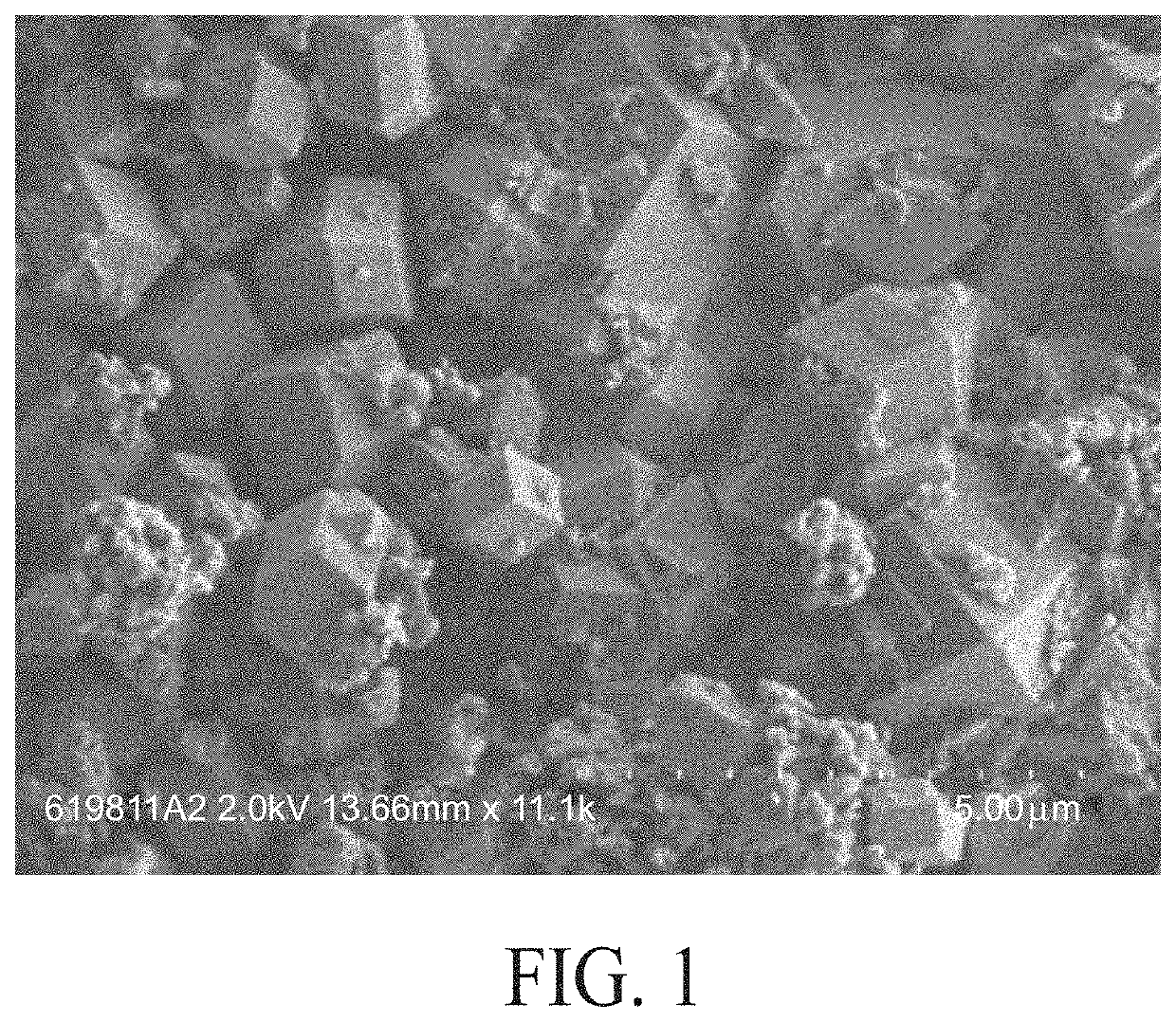
  • Highly Siliceous Form of Zeolite RHO
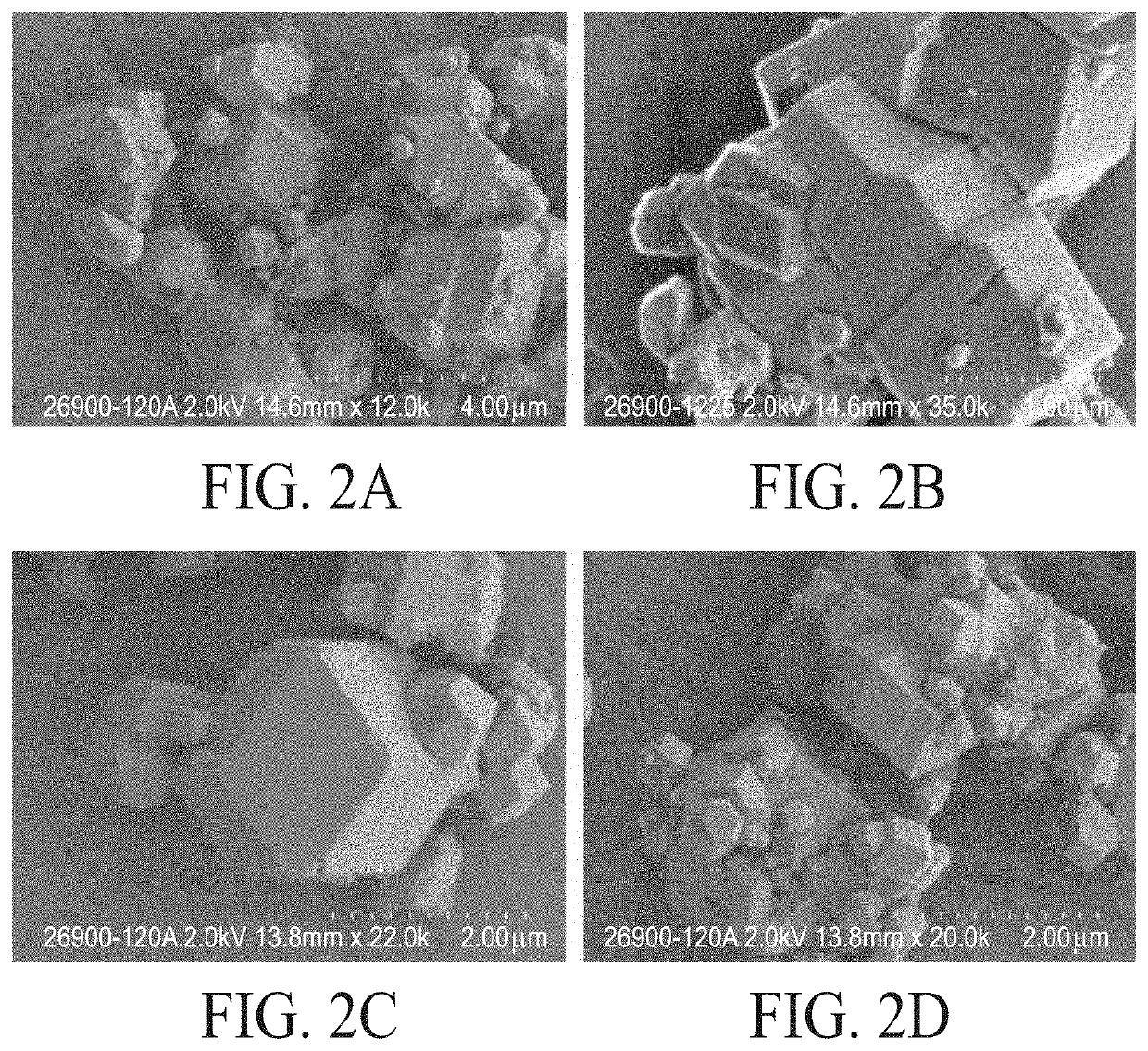
  • Highly Siliceous Form of Zeolite RHO
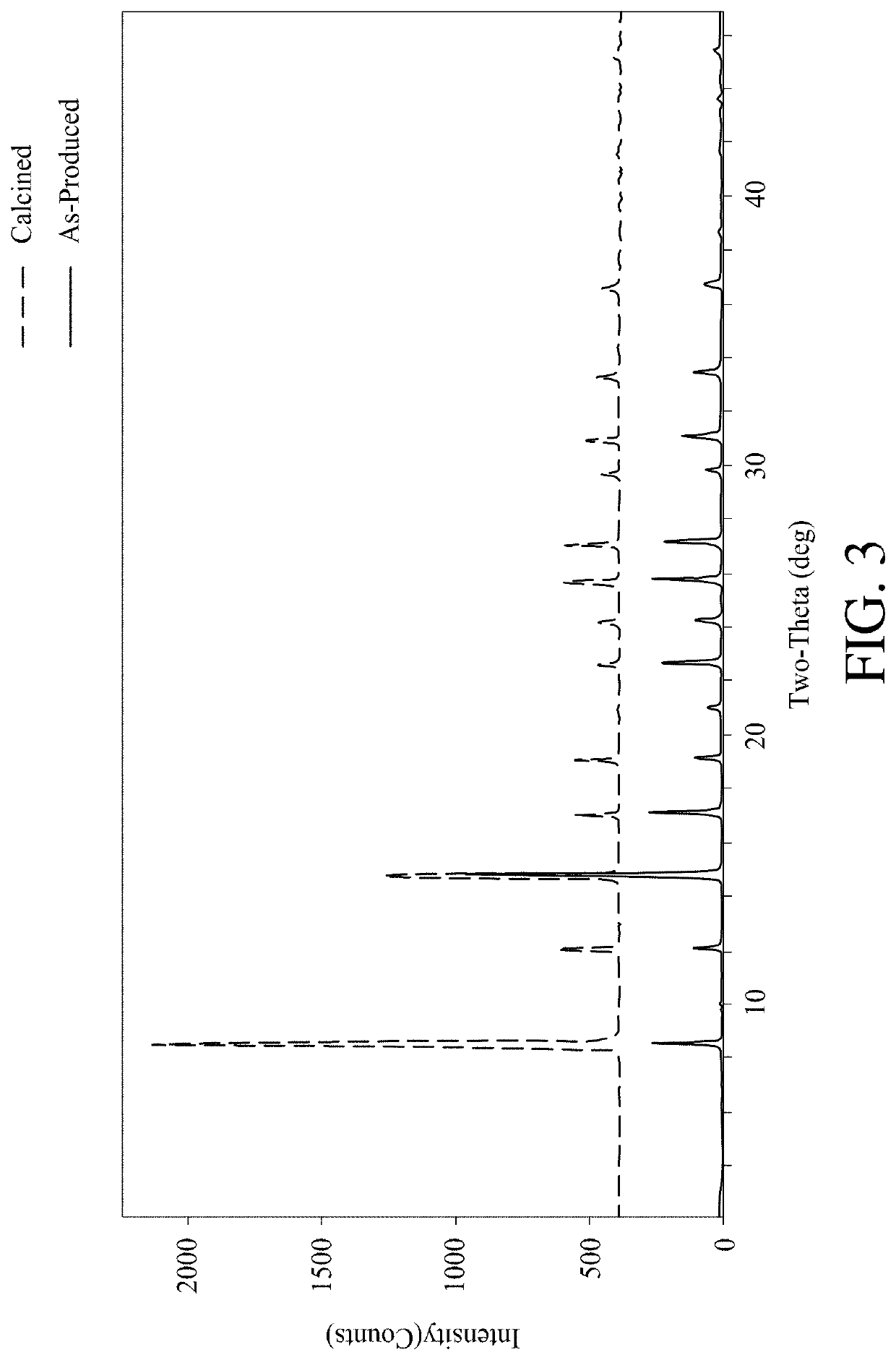
  • Highly Siliceous Form of Zeolite RHO

Examples


example embodiments

[0063]A first example embodiment of the present invention is a composition comprising: Rho zeolite with a RHO topology having a Si to B ratio or a Si to Al ratio greater than or equal to 8. This example embodiment can include one or more of the following: Element 1: wherein the Rho zeolite has a BET surface area about 800 m2 / g to about 1250 m2 / g; Element 2: wherein the Rho zeolite has micropore volume of about 0.25 cm3 / g to about 0.50 cm3 / g; Element 3: wherein the Rho zeolite has an average diameter of about 0.1 microns to about 25 microns; Element 4: in an as-synthesized form of a borosilicate Rho zeolite, an X-ray diffraction pattern including the d(Å) and relative intensities of Table 1; Element 5: wherein in a calcined or acid treated form of a borosilicate Rho zeolite, an X-ray diffraction pattern including the d-spacings d(Å) and relative intensities of Table 2; Element 6: wherein in an as-synthesized form of an aluminosilicate Rho zeolite, an X-ray diffraction pattern includi...

examples

[0073]Example 1. Reaction Scheme 1 illustrates the synthesis of Compound II. 200 mL of anhydrous THF was cannulated into a 500 mL flame dried round bottom with a stir bar. 3.965 g (30.0 mmol) of 2-methylbenzimidazole was added to the flask, then the flask was purged with nitrogen. Reaction mixture was cooled to −78 degrees Celsius. 12.0 mL (30.0 mmol, 1.0 eq) of 2.5M N-butyllithium added to the reaction mixture and stirred at −78 degrees Celsius for 5 minutes before returning to room temperature and stirring for 15 minutes at room temperature. 12.77 g (90.0 mmol, 3.0 eq) of iodomethane added and reaction stirred at room temperature for 16 hours. The light brown reaction mixture was poured into 150 mL of DI water and extracted 2× with 75 mL ethyl acetate and 2× with 75 mL methylene chloride. Combined organic layers were dried with sodium sulfate, gravity filtered into a pre-weighed round bottom, and solvent was removed by vacuum to yield product as a beige solid (3.04 g, 69.3% yield)...


PUM

PropertyMeasurementUnit
Temperatureaaaaaaaaaa

Abstract

A composition can include a Rho zeolite with a RHO topology having a Si to B ratio or a Si to A1 ratio greater than or equal to 8. Making such a composition can include heating an aqueous reaction mixture having a molar ratio of atomic Si to atomic B of about 4 to about 50 or a molar ratio of atomic Si to atomic Al of about 4 to about 50 in the presence of a C4-C6 diquat of N,2-dimethylbenzimidazole structure directing agent to a temperature of at least 75° C. to produce a Rho zeolite.

Description

BACKGROUND OF THE INVENTION[0001]Gas separation is important in various industries and can typically be accomplished by flowing a mixture of gases over an adsorbent that preferentially adsorbs a more readily adsorbed component relative to a less readily adsorbed component of the mixture. One of the more important gas separation techniques is pressure swing adsorption (PSA). PSA processes rely on the fact that under pressure gases tend to be adsorbed within the pore structure of microporous adsorbent materials or within the free volume of polymeric materials. The higher the pressure, the more gas is adsorbed. When the pressure is reduced, the adsorbed gas is released, or desorbed. PSA processes can be used to separate gases from a mixture of gases because different gases tend to fill the micropores or free volume of the adsorbent to different extents. For example, if a gas mixture such as natural gas is passed under pressure through a vessel containing polymeric or microporous adsorb...

Claims


Application Information

Patent Timeline
IPC IPC(8): C01B39/48B01D53/047B01J20/18
CPCC01B39/48B01D53/047B01J20/186C01P2006/12C01P2006/14C01P2002/74B01D2253/306B01D2256/245C01P2002/72C01P2006/16B01D2253/116B01D2253/311B01D2257/504B01J20/18B01J29/70B01J20/28057B01J20/28069B01D53/02B01D2253/1085C01B39/12C01B37/007B01J2229/186B01J29/86B01D53/8628Y02P20/151B01J35/30B01J35/40Y02C20/40
Inventor FALKOWSKI, JOSEPH M.VROMAN, HILDA BOUZABURTON, ALLEN W.TEREFENKO, EUGENEMAO, KANMISTROHMAIER, KARL G.
Owner EXXON RES & ENG CO
Learn More