Super-hydrophilic surface treatment method of filtration medium, super-hydrophilic filter for oil-water separation and method of fabricating the same

a technology of superhydrophilicity and surface treatment, which is applied in the direction of filtration separation, membranes, separation processes, etc., can solve the problems of poor treatment efficiency, and easy loss of hydrophilicity of hydrophilic surface body, and achieves easy fabrication, excellent superhydrophilicity and superoleophobicity in water, and the effect of easy surface treatment process

Inactive Publication Date: 2022-04-21
POSTECH ACAD IND FOUND
View PDF1 Cites 2 Cited by
  • Summary
  • Abstract
  • Description
  • Claims
  • Application Information

AI Technical Summary

Benefits of technology

[0051]Because the super-hydrophilic filter for oil-water separation according to the present invention has excellent super-hydrophilicity and super-oleophobicity in water due to its stable hydrophilic layer, and also has a self-cleaning ability, the super-hydrophilic filter may be washed in water even when it is contaminated with oil. Also, it is possible to selectively recover high-purity water in the mixture of water and oil due to the selective wettable property, and it is possible to apply the super-hydrophilic filter to purify the emulsion stabilized with the surfactant. In addition, when the filter used is immersed in water for 30 seconds, the filter may be cleanly washed and reused for oil-water or emulsion separation.
[0052]Meanwhile, for the above-described super-hydrophilic filter for oil-water separation, the oil-water mixture separation performance and the emulsion separation performance may be controlled through the nominal size of the filter. Because the surface treatment method or the coating method according to an exemplary embodiment of the present invention is applicable to various materials and bases having a nominal size, the oil-water separation performance (separation efficiency or processing speed) may be controlled, and thus appropriate bases may be selected to secure a desired level of oil-water separation performance, thereby satisfying the requirements for various oily wastewater treatment according to the conditions.
[0053]According to the method of fabricating a super-hydrophilic filter for oil-water separation according to the present invention, a stable hydrophilic polymer layer may be formed on various bases, such as a polymer, a metal, a super-hydrophobic base, and the like, through single-step coating, and a super-hydrophilic filter which does not come into contact with oil in water may be easily fabricated. Also, because the surface treatment process is very simple, it is easy to fabricate a large super-hydrophilic filter, and the super-hydrophilic filter may be mass-produced using a roll-to-roll technique.
[0054]As a result, the method of fabricating a super-hydrophilic filter according to the present invention has an advantage in that it is easy to fabricate a large filter and mass-produce the filter. Therefore, the method of fabricating a super-hydrophilic filter according to the present invention may be effectively used in the industries actually requiring the oily wastewater treatment.

Problems solved by technology

In such a method, however, the oil is easily separated when oil drops have a size of 1 mm or more, but the oil drops having a diameter of 1 to 1.5 μm, which have split into small pieces due to the flow of a fluid, have poor treatment efficiency because it takes a long time to separate the oil by floating and congelation.
However, when oil is used for a long time in such a method, sludge having viscosity, to which oily components and floating matters are attached are deposited between the corrugated cardboards and the eggbox panels which are coupled in a multi-stage manner to prevent the passage of a fluid.
However, because such materials exhibit high reactivity with other chemical functional groups, they easily lose their hydrophilicity when they lose their hydrophilic functional group.
Also, a hydrophilic surface body may be prepared using chemically stable nanoparticles such as titanium dioxide (TiO2), silicon dioxide (SiO2), but the materials have drawbacks in that the hydrophilic surface body easily loss its hydrophilicity due to weak binding affinity for bases.
This treatment method has limitations in that it is time consuming, requires treatment facilities having a wide area, and has poor oil-water separation efficiency.
Also, a surfactant-stabilized emulsion cannot be separated using the difference in specific gravity.
However, the emulsion treatment method using such a demulsified drug or electricity is difficult to use in industries because an amount of the drug or electrical energy applied should be controlled with high precision, and a limited amount of the emulsion may be processed per hour.
However, when the super-hydrophobic filter is used, a surface of the filter may be contaminated while the oil passes through the filter, which results in deteriorated oil-water separation performance.
However, a super-hydrophilic filter medium for oil-water separation may be directly fabricated using an electrospinning method, and the like, but such a method has limitations in that it takes a long time to fabricate a filter, requires special equipment and technology, is very expensive, and is difficult to apply to the industry because it is difficult to produce and mass-produce a large-area filter.
However, such filters are difficult to surface-treat, and exhibit hydrophobicity.
However, because different surface treatment techniques should be applied according to materials for the base in order to fabricate a super-hydrophilic filter, these techniques has a difficulty in fabricating a super-hydrophilic filter in the industry requiring the use of filters made of various materials.
Also, the super-hydrophilic modification process is complicated, and thus has limitations in that it is difficult to fabricate a large-area super-hydrophilic filter and it is difficult to mass produce the super-hydrophilic filter.

Method used


Image

  • Super-hydrophilic surface treatment method of filtration medium, super-hydrophilic filter for oil-water separation and method of fabricating the same
  • Super-hydrophilic surface treatment method of filtration medium, super-hydrophilic filter for oil-water separation and method of fabricating the same
  • Super-hydrophilic surface treatment method of filtration medium, super-hydrophilic filter for oil-water separation and method of fabricating the same

Examples


example 1

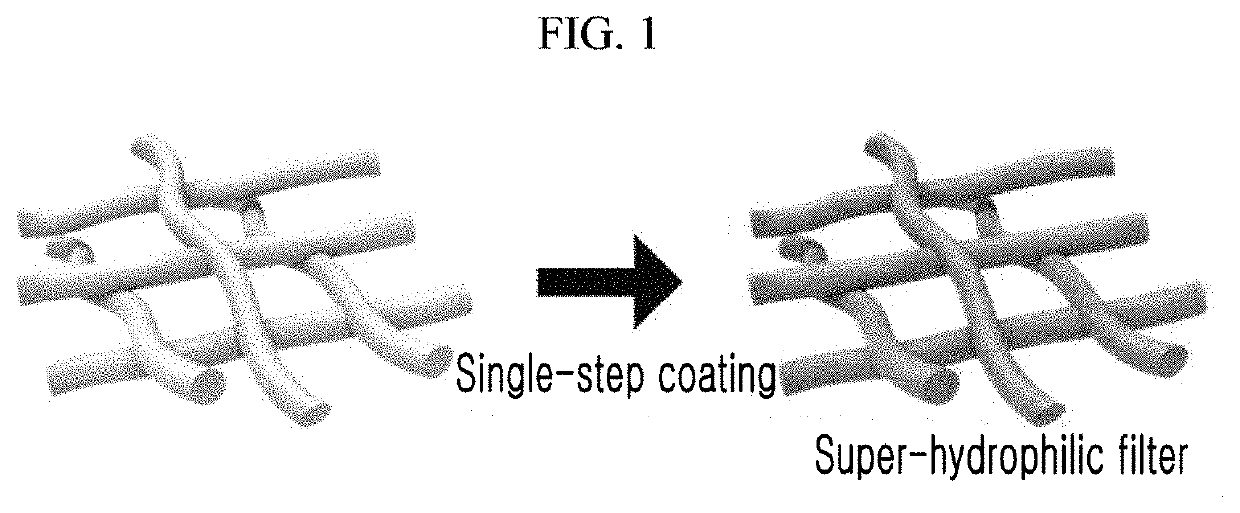
on of Super-Hydrophilic Filter According to Single-Step

[0072]Coating Process

[0073]1-1: Preparation of Filtration Filter

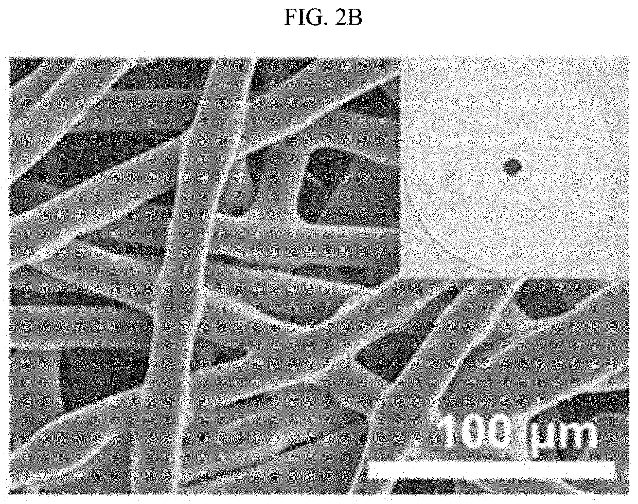
[0074]To fabricate a super-hydrophilic filter, a commercially available polyethylene (PE) filter (a membrane filter having a diameter of 47 mm and a nominal pore size of 10 μm; Pall Life Science (USA)) which was not surface-treated was prepared. An SEM photograph of the polyethylene filter before surface treatment is shown in FIG. 2B. Here, polymer fibers and pores formed by cross-linking the polymer fibers are shown. Such a general commercial PE filter has hydrophobicity due to the presence of a methyl group having a low surface tension with respect to the microsized fibers.

[0075]1-2: Formation of Hydrophilic Coating Layer

[0076]The prepared polyethylene (PE) filter was immersed in an aqueous ethanol solution at 20° C. for 10 seconds, and then immersed in a mixed solution including bis-acrylamide (N,N-methylenebisacrylamide) as a cross-linking agent and ammonium per...

example 2

n of Characteristics of Polymer Filters During Formation of Coating Layer

[0078]2-1: Spectroscopic Analysis of Filter

[0079]For a conventional polyethylene (PE) filter and a filter composed of polyethylene fibers having a surface product obtained by the process, it was evaluated whether a functional group was formed using Fourier transform infrared spectroscopy.

[0080]Based on the results of evaluating the formation of the functional group using Fourier transform infrared spectroscopy as obtained in FIG. 2A, the conventional untreated PE filter had characteristic peaks at 1,472, 2,847, and 2,914 cm−1, as widely known in the art. After the single-step coating, the characteristic peaks were further observed at 1,538, 1,652, and 3,296 cm−1, indicating the hydrophilic functional groups, for example, C═O, C═O, and N—H bonds.

[0081]2-2: Evaluation of Hydrophilicity of Filter

[0082]A polymer base, a metal base, and a super-hydrophobic base were subjected to the coating method according to the p...

example 3

on of Large Super-Hydrophilic Filter

[0087]A photograph of a large super-hydrophilic filter with a size of 400 mm×1,000 mm fabricated by the surface treatment process according to the present invention is shown in FIG. 5. The large super-hydrophilic filter was fabricated using a stainless steel mesh (TWP Inc.) as the base, and a mesh base with a length of 400 mm and a width of 1,000 mm was identical to the stainless steel mesh used in Example 2. Because the surface treatment process was applied to a simple immersion method as a single coating process, a large super-hydrophilic filter was able to be easily fabricated.


PUM

PropertyMeasurementUnit
contact angleaaaaaaaaaa
diameteraaaaaaaaaa

Abstract

A super-hydrophilic surface treatment method of a filter medium of a filter for oil-water separation according to the present invention includes preparing a filter medium or a filter including the filter medium using a polymer base or a metal base, and forming a hydrophilic coating layer to the filter medium or the filter including the filter medium by cross-linking bis-acrylamide (N,N-methylenebisacrylamide).

Description

CROSS-REFERENCE TO RELATED APPLICATION[0001]This application claims priority to and the benefit of Korean Patent Application No. 10-2020-0136945 filed in the Korean Intellectual Property Office on Oct. 21, 2020, the entire contents of which are incorporated herein by reference.BACKGROUND OF THE INVENTION(a) Field of the Invention[0002]The present disclosure relates to a super-hydrophilic surface treatment method, a super-hydrophilic filter for oil-water separation, which has a surface super-hydrophilically modified using the same, and a method of fabricating the same.(b) Description of the Related Art[0003]In general, oil-water separation facilities configured to separate oily components contained in water or moisture in oil from oil components and non-point pollutants introduced through wastewater treatment plants or stormwater pipes, and non-point pollution reduction facilities (initial rainwater treatment facilities) use a removal method using a difference in specific gravity bet...

Claims


Application Information

Patent Timeline
Patent Type & Authority Applications(United States)
IPC IPC(8): B01D17/04B01D69/02B01D39/16B01D39/20B01D67/00C02F1/40
CPCB01D17/045B01D69/02B01D39/16B01D39/2027B01D67/0088C02F2101/32B01D2325/36B01D2239/0421B01D2239/0478B01D2239/10B01D2323/02C02F1/40B01D39/10B01D39/1623B01D2239/0492B01D2239/0464B01D2239/1216B01D67/0093B01D2323/30B01D67/0006B01D69/12B01D71/40B01D17/08C02F2101/325C02F1/004B01D71/06B01D71/022
Inventor HWANG, WOONBONGKIM, SEONGMIN
Owner POSTECH ACAD IND FOUND
Why Eureka
Try Eureka