Etching method for oxide semiconductor film
a technology of oxide semiconductor film and etching method, which is applied in the direction of semiconductor devices, electrical equipment, radio frequency controlled devices, etc., can solve the problems of deterioration of the characteristics of devices including change in the composition of the oxide semiconductor film, etc., and achieves less molecular weight, less bonding, and less insulation property
- Summary
- Abstract
- Description
- Claims
- Application Information
AI Technical Summary
Benefits of technology
Problems solved by technology
Method used
Image
Examples
first embodiment
1. First Embodiment
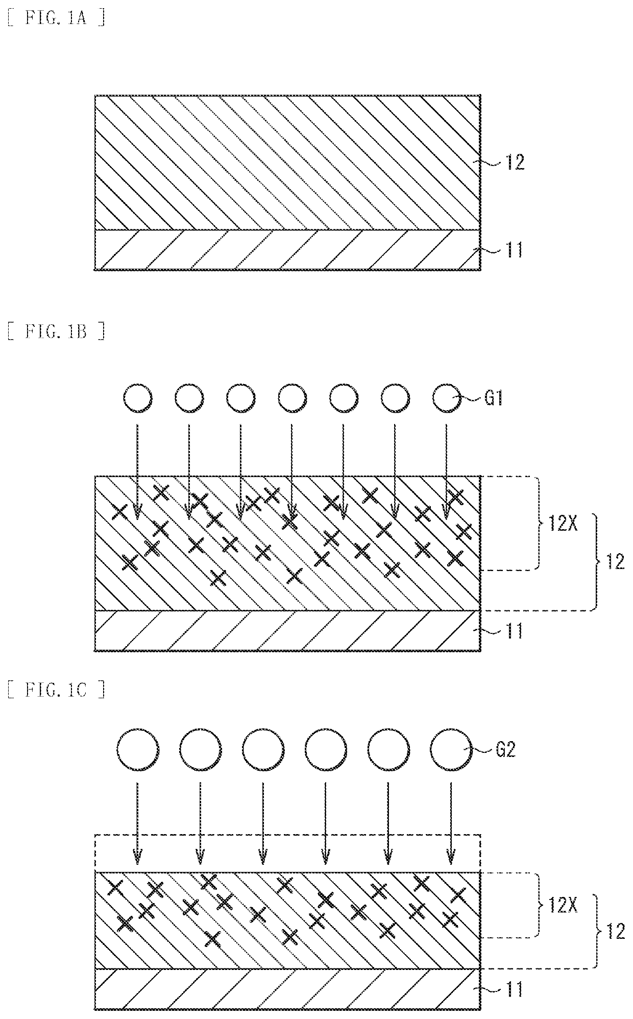
[0038]Each of FIGS. 1A to 1C is a cross-sectional schematic diagram illustrating an etching step for an oxide semiconductor film (oxide semiconductor film 12) according to a first embodiment of the present disclosure. The oxide semiconductor film 12 is used, for example, as an electrode included in any of various displays such as a flat panel display and a touch panel and devices such as a solar cell and a light emitting diode (Light Emitting Diode; LED). Additionally, the oxide semiconductor film 12 is also used for an electromagnetic shield, an anti-reflection film, and the like. The etching method according to the present disclosure is favorably used, for example, to pattern the oxide semiconductor film 12 included in an electrode.
(1-1. Etching Method for Oxide Semiconductor)
[0039]In the etching method for the oxide semiconductor film 12 according to the present embodiment, a modification is made by using a rare gas G1 (first rare gas) to form a modified layer ...
second embodiment
2. Second Embodiment
[0054]Each of FIGS. 5A and 5B is a cross-sectional schematic diagram illustrating an etching step for an oxide semiconductor film (oxide semiconductor film 12) according to the second embodiment of the present disclosure. In an etching method for the oxide semiconductor film 12 according to the present embodiment, a mixture of the two types of rare gases of the rare gas G1 and the rare gas G2 is used to form and sputter the modified layer 12X of the oxide semiconductor film 12 in one step. The following describes the etching method for the oxide semiconductor film 12 with reference to FIGS. 5A and 5B.
[0055]First, as illustrated in FIG. 5A, the oxide semiconductor film 12 is formed on a supporting base material 11 by using, for example, a dry method or a wet method as in the first embodiment described above. Subsequently, as illustrated in FIG. 5B, a mixture gas is radiated that is obtained, for example, by mixing the rare gas G1 and the rare gas G2, for example, ...
third embodiment
3. Third Embodiment
[0058]Each of FIGS. 6A to 6C is a cross-sectional schematic diagram illustrating an etching step for an oxide semiconductor film (oxide semiconductor film 12) according to the third embodiment of the present disclosure. The etching method for the oxide semiconductor film 12 according to the present disclosure is used, for example, for any of various devices, an electromagnetic shield, an anti-reflection film, and the like as described above. For example, in relation to displays, the etching method is favorably used to process electrodes, thin film transistors (TFTs), and color filters included in a TN (Twist Nematic) liquid crystal display and an STN (Super Twist Nematic) liquid crystal display, an OLED (Organic Light Emitting Diode), a PDP (Plasma Display Panel), an FED (Field Emission Display), and an electronic paper. The following describes an example of the specific etching method for the oxide semiconductor film 12 with reference to FIGS. 6A to 6C.
[0059]Firs...
PUM
| Property | Measurement | Unit |
|---|---|---|
| Binding energy | aaaaa | aaaaa |
| Binding energy | aaaaa | aaaaa |
| speed | aaaaa | aaaaa |
Abstract
Description
Claims
Application Information
 - R&D
- Intellectual Property
- Life Sciences
- Materials
- Tech Scout
- Unparalleled Data Quality
- Higher Quality Content
- 60% Fewer Hallucinations
Browse by: Latest US Patents, China's latest patents, Technical Efficacy Thesaurus, Application Domain, Technology Topic, Popular Technical Reports.
© 2025 PatSnap. All rights reserved.Legal|Privacy policy|Modern Slavery Act Transparency Statement|Sitemap|About US| Contact US: help@patsnap.com


