Lithium metal anode, method for manufacturing same, and lithium secondary battery using same

a lithium secondary battery and lithium metal anode technology, applied in the manufacturing process of electrodes, cell components, electrochemical generators, etc., can solve the problems of shortening the cycle life of the battery, shortening the battery cycle, and being extremely inefficient and uneconomical, so as to reduce the time required for the pre-lithiation process, reduce the mobility of lithium ions, and reduce the ionic conductivity of the electrolyte solution

Pending Publication Date: 2022-05-12
POSCO HLDG INC +1
View PDF0 Cites 0 Cited by
  • Summary
  • Abstract
  • Description
  • Claims
  • Application Information

AI Technical Summary

Benefits of technology

[0056]Meanwhile, the electrolyte solution may include a general non-aqueous solvent as a solvent in consideration of the viscosity of the plating solution. If the viscosity of the electrolyte solution is too high, mobility of lithium ions decreases and ionic conductivity of the electrolyte solution decreases. Therefore, the time required for the pre-lithiation process may increase, thereby reducing productivity.

Problems solved by technology

When lithium metal is used as an anode material, there are problems of causing an electrical short circuit due to dendrite formed during the charge and discharge and shortening a battery cycle-life due to cracks generated by mechanical stress caused by repeated contractions and expansion of the anode material.
However, this method requires advanced process technology over development, etching, etching, and the like based on semiconductor technology and high cost and thus is extremely inefficient and uneconomical.
However, since the three-dimensional concavo-convex structure formed by applying the physical pressure has too a wide interval of the concavo-convex portion within a range of tens to hundreds of micrometers and also, too a deep depth of the convex portion within a range of tens to hundreds of micrometers, securing the accommodation space through implementing the three-dimensional structure may be very localized.
In particular, in order to obtain the desired effects, since the convex portion should be formed deep, lithium metal having a thickness of hundreds of micrometers or more may have the aforementioned concavo-convex portion, but since lithium used for a high energy density lithium battery should have a thin thickness of 10 μm to 50 μm, the aforementioned concavo-convex portion may not be easy to form in this thin film lithium.

Method used


Image

  • Lithium metal anode, method for manufacturing same, and lithium secondary battery using same
  • Lithium metal anode, method for manufacturing same, and lithium secondary battery using same
  • Lithium metal anode, method for manufacturing same, and lithium secondary battery using same

Examples


experimental examples

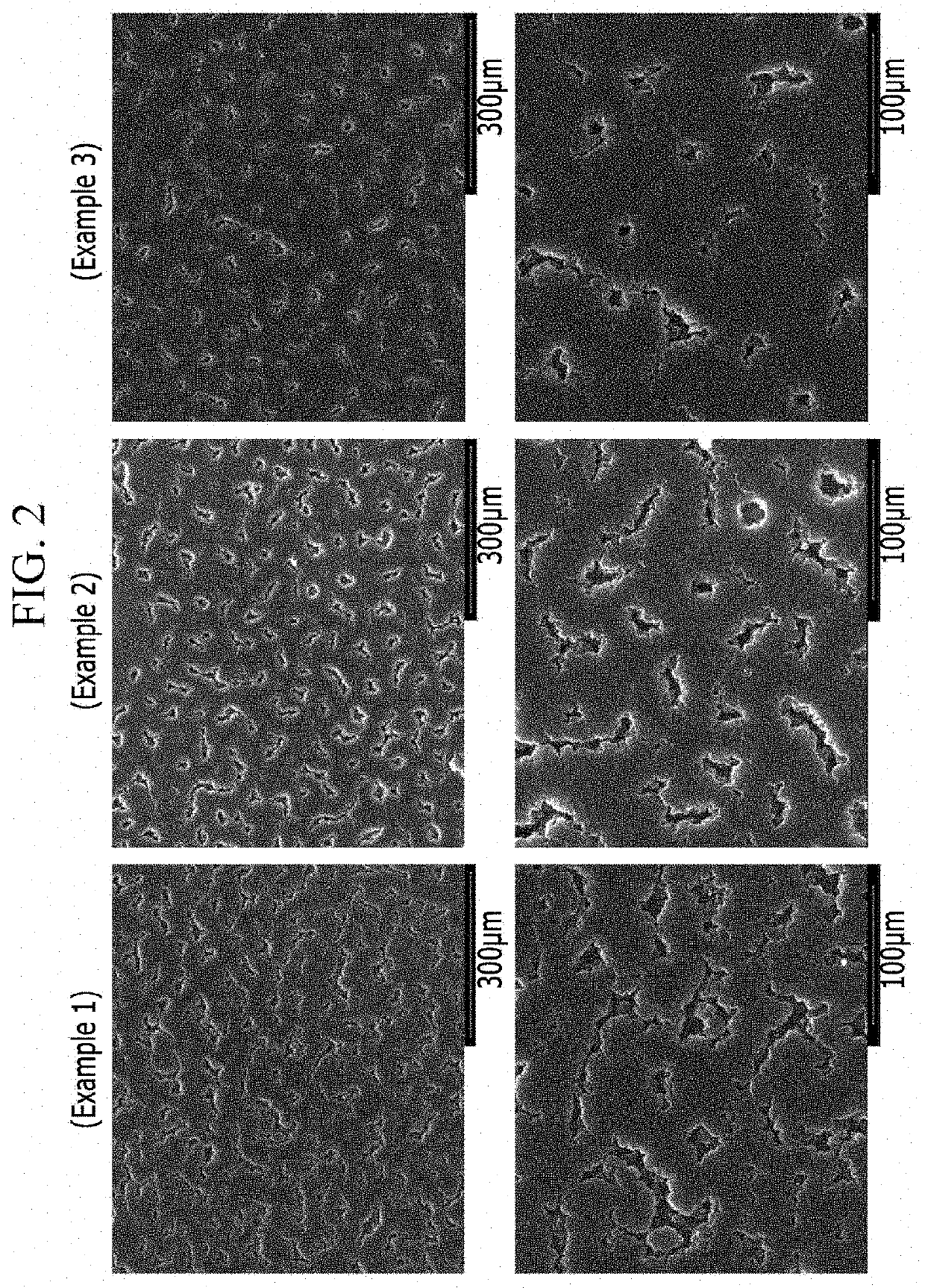
[0101]FIG. 2 shows shapes of the microstructures of the surfaces of the lithium metals controlled in Examples 1, 2, and 3. In the lithium metal thin films having the same thickness of about 20 μm, the microstructures with different porosity and the resulting different concavo-convex shapes were formed.

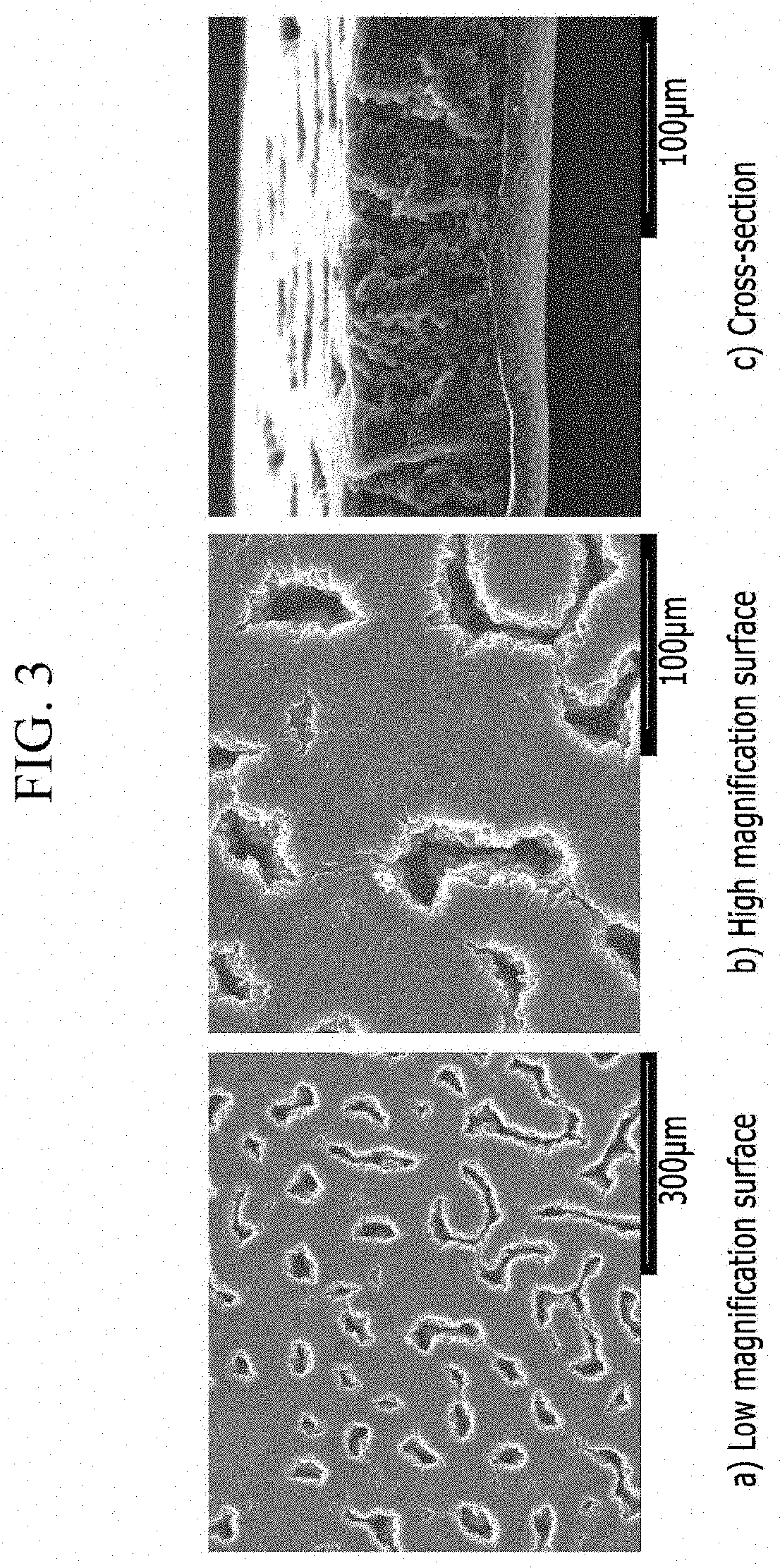
[0102]FIG. 3 shows the surface and cross-sectional microstructures of the an 100 μm-thick lithium metal foil formed according to Example 4.

[0103]Even though the lithium metal became thicker, a three-dimensional porous structure was formed with no dendrite formation by adjusting the current and time factors of the electroplating process.

[0104]On the other hand, FIG. 4 shows Comparative Example 1, a case of having an extremely high pore fraction, since lithium metal was insufficiently formed by the electroplating and thus not formed on a large portion out of the entire area. In addition, at the edges of particles, lots of dendrites were formed.

[0105]FIG. 5 shows a structure in which lith...


PUM

PropertyMeasurementUnit
thicknessaaaaaaaaaa
current densityaaaaaaaaaa

Abstract

The present invention relates to a lithium metal anode, a method for manufacturing same, and a lithium secondary battery using same. The lithium metal anode include a current collector having a flat structure and an anode active material layer including a lithium metal disposed on the current collector, wherein the lithium metal has a concave-convex structure and no dendrite is present on the surface of the lithium metal.

Description

TECHNICAL FIELD[0001]A lithium metal anode, a method for manufacturing the same, and a lithium secondary battery using the same are disclosed.BACKGROUND ART[0002]In order to achieve a lower price but a higher energy density of a secondary battery, a lithium metal electrode has been proposed as an anode thereof.[0003]When lithium metal is used as an anode material, there are problems of causing an electrical short circuit due to dendrite formed during the charge and discharge and shortening a battery cycle-life due to cracks generated by mechanical stress caused by repeated contractions and expansion of the anode material.[0004]In order to overcome these problems, an attempt to develop a lithium anode material having a three-dimensional structure to secure a free space for lithium growth but suppress growth of the dendrite during the charge and discharge has been made.[0005]KR10-2010-0114321 discloses a method of suppressing the dendrite growth by using a patterned silicon substrate ...

Claims


Application Information

Patent Timeline
Patent Type & Authority Applications(United States)
IPC IPC(8): H01M4/134H01M4/1395H01M4/04H01M10/0525
CPCH01M4/134H01M4/1395H01M2004/027H01M10/0525H01M4/0452H01M10/052Y02E60/10H01M4/382H01M2004/021H01M4/045H01M4/62
Inventor BAE, HONGYOULKIM, JIN HONGLEE, SIHWABAE, WEON SOOLEE, SANG LAG
Owner POSCO HLDG INC
Why Eureka
Try Eureka