
A method of abating carbon dioxide and hydrogen sulfide

a technology of which is applied in the field of abating carbon dioxide and hydrogen sulfide, can solve the problems of high price of cosub>2 /sub>, colorless, toxic and toxic hydrogen sulfide, and the characteristic odor of rotten eggs

Pending Publication Date: 2022-07-14
CARBFIX +3
View PDF2 Cites 0 Cited by
  • Summary
  • Abstract
  • Description
  • Claims
  • Application Information

AI Technical Summary

Benefits of technology

The present invention provides a method to capture, transport, and store gas mixtures containing carbon dioxide (CO2) and hydrogen sulfide (H2S) at deep geological sites. The method has the advantage of being cost-effective when compared to conventional technologies. The overall cost of the method is significantly lower than the reported cost of other methods. The method involves pumping water into an injection well and injecting a CO2 and / or H2S rich gas into another injection well, resulting in a dissolved gas stream. This gas stream is then transported to a storage site.

Problems solved by technology

Both gasses present important challenges to the environment.
However, as climate change policy becomes stricter this might change and it is predicted that the price of emitting CO2 will rise.
Hydrogen sulfide is a colorless, flammable and toxic gas with the characteristic odor of rotten eggs.
Exposure to it can cause health problems depending on levels and duration of exposure.
Low level, prolonged exposure can cause inflammation and irritation of the eyes whereas high levels of exposure for brief periods of time can cause dizziness, headache, nausea and even death if the concentration of H2S in atmosphere goes above 300 ppm.
The hydrogen sulfide is carried by wind away from the site of the power plant and can under some weather conditions cause foul smell in nearby communities.
This implies that it was apparently not fully understood by the authors of these publications at that point in time exactly which factors may in fact affect the usefulness of such methods.
The value of these products is low as there is either too little demand or excess supply.
Disposal of these products is costly and can create environmental problems.
However, until now neither has such a method of abating hydrogen sulfide been described in detail, nor is it fully understood which factors may in fact affect the usefulness of such a method.

Method used

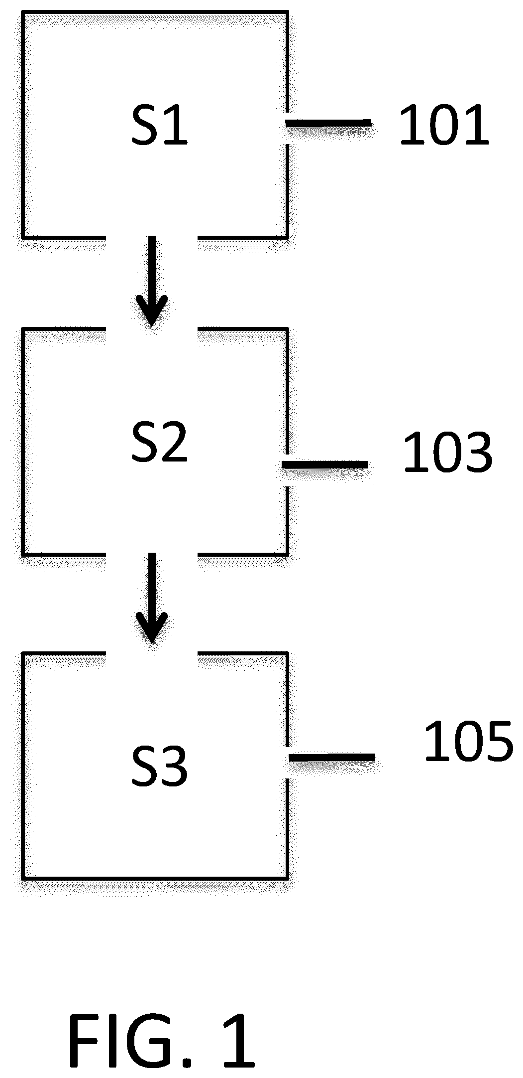
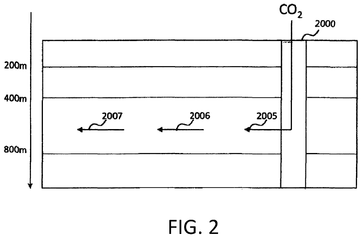

Image

  • A method of abating carbon dioxide and hydrogen sulfide
  • A method of abating carbon dioxide and hydrogen sulfide
  • A method of abating carbon dioxide and hydrogen sulfide

Examples


example 1

[0148]0.07 kg / s of CO2 comes from the gas purification unit or a gas separation station of a geothermal power plant. The initial pressure of the gas is 30 bar. For the transportation of the gas to the injection well a pipe is selected with outer diameter (OD) 40 mm, resulting in a pressure drop of 1.45 bar. Including other pressure losses it is assumed that the pressure at the well head is 28 bar. For the injection a pipe with OD 32 mm is selected resulting in pressure drop of 0.41 bar, but due to gravity the pressure head at the merging point will increase by 1.1 bar and the pressure at the merging point will be 28.6 bar.

[0149]The injection pipe is a pipe with OD 75 mm and needs a volumetric flow rate of 1.94 kg / s of water to dissolve the gaseous carbon dioxide. The pressure drop under those conditions is 0.51 bar / 100 m. Therefore, the water column in the injection pipe will be approximately 13 m above the water level in the well due to the pressure drop down to the merging point. ...

example 2

[0151]In this example, the partial pressure of carbon dioxide is selected to be 25 bar downhole. This means saturation at 25 bar pressure or 36 g CO2 pr. kg water at 17° C. At this temperature and pressure the volume of carbon dioxide is approximately 20 times the volume of the equivalent mass of water at atmospheric pressure. For the water to be able to pull the gas downwardly, the volume of the gas should not exceed the volume of the water, preferably be much smaller. For the water to be able to bring the gas downward in the pipe, the water pressure at the gas release point (merging point) should preferably be near the saturation pressure of 25 bar. If however a sufficient volumetric water flow rate is maintained it is possible to have the pressure lower. Part of the gas will dissolve in the water and the remaining gas will form small bubbles and travel with the water down the pipe. As the depth increases the bubbles become smaller as the pressure increases and the gas continues t...

example 3

[0152]In this embodiment, shown in FIG. 10, a monitoring well 610 is interlinked to the injection well 612 via a flow path 614, which may e.g. be a fracture in the geological reservoir. The implementation of this monitoring well 610 is to estimate the mineralization capacity of the CO2. The step of estimating comprises using one or more tracer substances for tracing the CO2 gas, or the water, or the carbon. Thus, one or more types of tracers may be added via an appropriate tracer source for tracing one or more of these in a controllable way such that the molar ratio between the CO2 gas, or the water, or the carbon, and the tracer substance(s) is pre-determined, i.e. the molar ratio is prefixed. This means that only one tracer can be used for tracing e.g. only CO2, or only C, or only water, or a combination thereof. As an example, SF5CF3 tracer, SF6 tracer or Rhodamine tracer may be implemented to track the dilution between the injected fluid and the ambient water in the reservoir as...


PUM

PropertyMeasurementUnit
pressureaaaaaaaaaa
pressureaaaaaaaaaa
pressureaaaaaaaaaa

Abstract

This invention relates to a method and a system of abating carbon dioxide (CO2) and / or hydrogen sulfide (H2S) in a geological reservoir. Water is pumped or transferred from a water source to an injection well. The gasses are merged with the water under conditions where the hydraulic pressure of the water is less than the pressure of CO2 and / or H2S gas at the merging point. The water with CO2 and / or H2S gas bubbles is transferred further downwardly at a certain velocity higher than the upward flow velocity of said CO2 and / or H2S gas bubbles ensuring downward movement of gas bubbles resulting in full dissolution of said CO2 and / or H2S in the water due to elevating pressure. The complete dissolution ensures a lowered pH of the water entering a geological (e.g. geothermal) reservoir which is needed to promote mineral reactions leading to CO2 and H2S abatement This abatement may be quantified by dissolving a tracer substance in a predetermined molar ratio to said dissolved CO2 and / or H2S and monitored in a monitoring well.

Description

FIELD OF THE INVENTION[0001]The present invention relates to a method and a system for abating carbon dioxide (CO2) and / or hydrogen sulfide (H2S) by injecting these into and subsequently storing these in a geological reservoir.BACKGROUND OF THE INVENTION[0002]Carbon dioxide (CO2) and hydrogen sulfide (H2S) are two gasses often released in large quantities during a wide range of industrial processes, e.g. combustion of fossil fuels. Both gasses present important challenges to the environment.[0003]The reduction of industrial CO2 emissions is one of the main challenges of this century (Ref. 1: Broecker and Kunzig). In general, CO2 emission is relatively low from geothermal resources and these are classified as renewable energy sources. This is in contrast to regular power plants that are run on fossil fuels which buy and sell pollution permits (called “allowances”).[0004]Conventional geothermal plants utilize the heat of the Earth by making use of a hot mixture of steam and brine from...

Claims


Application Information

Patent Timeline
Patent Type & Authority Applications(United States)
IPC IPC(8): B01D53/14E21B41/00E21B43/38E21B47/11
CPCB01D53/1475B01D53/1468B01D53/1493B01D2252/103E21B41/0064E21B43/38E21B47/11B01D53/1412B01D53/62B01D53/52B01D2257/304B01D2257/504B01D53/78Y02C20/40E21B43/164B65G5/00
Inventor SIGFÚSSON, BERGURARADÓTTIR, EDDA SIF PINDGUNNARSSON, INGVIARNARSON, MAGNUS PÓRGUNNLAUGSSON, EINARSIGURDARDÓTTIR, HÓLMFRIÐURSIGHVATSSON, HÚNIGÍSLASON, SIGURÐUR REYNIROELKERS, ERIC H.MESFIN, KIFLOM G.SNÆBJÖRNSDÓTTIR, SANDRA ÓSKGALECZKA, IWONA M.WOLFF-BOENISCH, DOMENIKALFREDSSON, HELGI A.JÓNSSON, PORSTEINNSTEFÁNSSON, ANDRIMATTER, JÜRGSTUTE, MARTINCLARK, DEIRDRE ELIZABETHVOIGT, MARTIN JOHANNES
Owner CARBFIX
Learn More