Eureka AIR delivers breakthrough ideas for toughest innovation challenges, trusted by R&D personnel around the world.

Aortic Stent

a technology of aortic valve and stent, which is applied in the field of stent, can solve the problems of affecting the hemodynamic functioning of the valve, affecting the integration of the native leaflets and the annulus, and affecting the hemodynamic function of the valve, and achieving the effect of reducing the risk of stent failur

Pending Publication Date: 2022-08-18
PF PROD FEATURES GMBH
View PDF9 Cites 0 Cited by
  • Summary
  • Abstract
  • Description
  • Claims
  • Application Information

AI Technical Summary

Benefits of technology

The patent text describes the use of biological tissues, such as bovine pericardium, to make heart valve and blood vessel replacements as well as pacing devices. The structure and composition of the tissue determine its behavior under loading. The device also has a knob that can be rotated to deflect and improve the positioning of the delivery device, leading to better accuracy of deployment and reduced stress over the system during deployment. Technical effects include improved outcomes and reduced complications during heart valve replacement surgery.

Problems solved by technology

In patients with aortic stenosis, the integrity of the native leaflets and the annulus is compromised primarily due to calcification.
A compromised valvular apparatus prevents the leaflets from fully opening during systole, thus affecting the hemodynamic functioning of the valve.
One drawback of existing technologies is leakage around the valve, termed paravalvular leakage (PVL).
However, biological tissues obtained from the abattoir, in particular porcine and bovine cadavers, begin to degrade immediately.
Therefore, the storage of such materials has proven to be difficult.
Calcification, in particular pathologic calcification, of soft biological tissues due to deposition of calcium phosphate mineral salts in an implanted tissue is undesirable and the deposition of the calcific deposits can have severe consequences on device performance.
Calcification of implants can lead to stiffening, structural instability and ultimately to device failure.
However, such tissue has altered mechanical property, early mechanical failure, cytotoxicity, and incomplete suppression of immunological recognition.

Method used


Image

  • Aortic Stent
  • Aortic Stent
  • Aortic Stent

Examples


Embodiment Construction

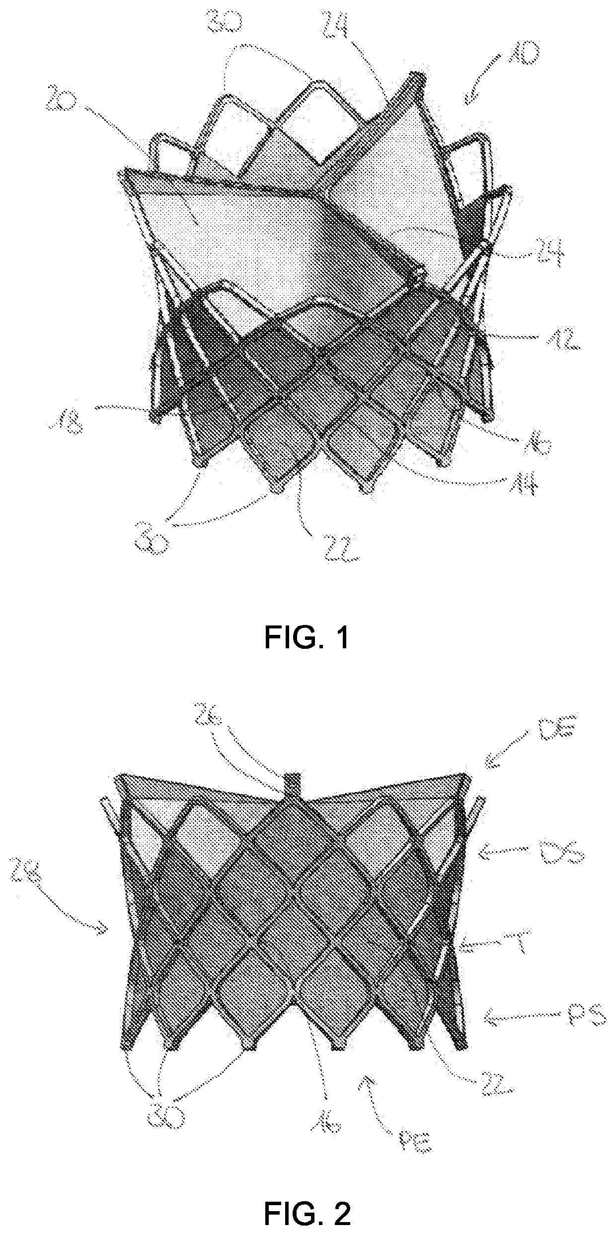
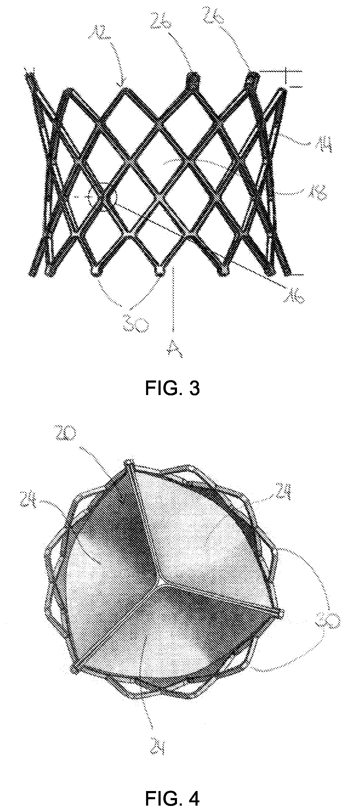
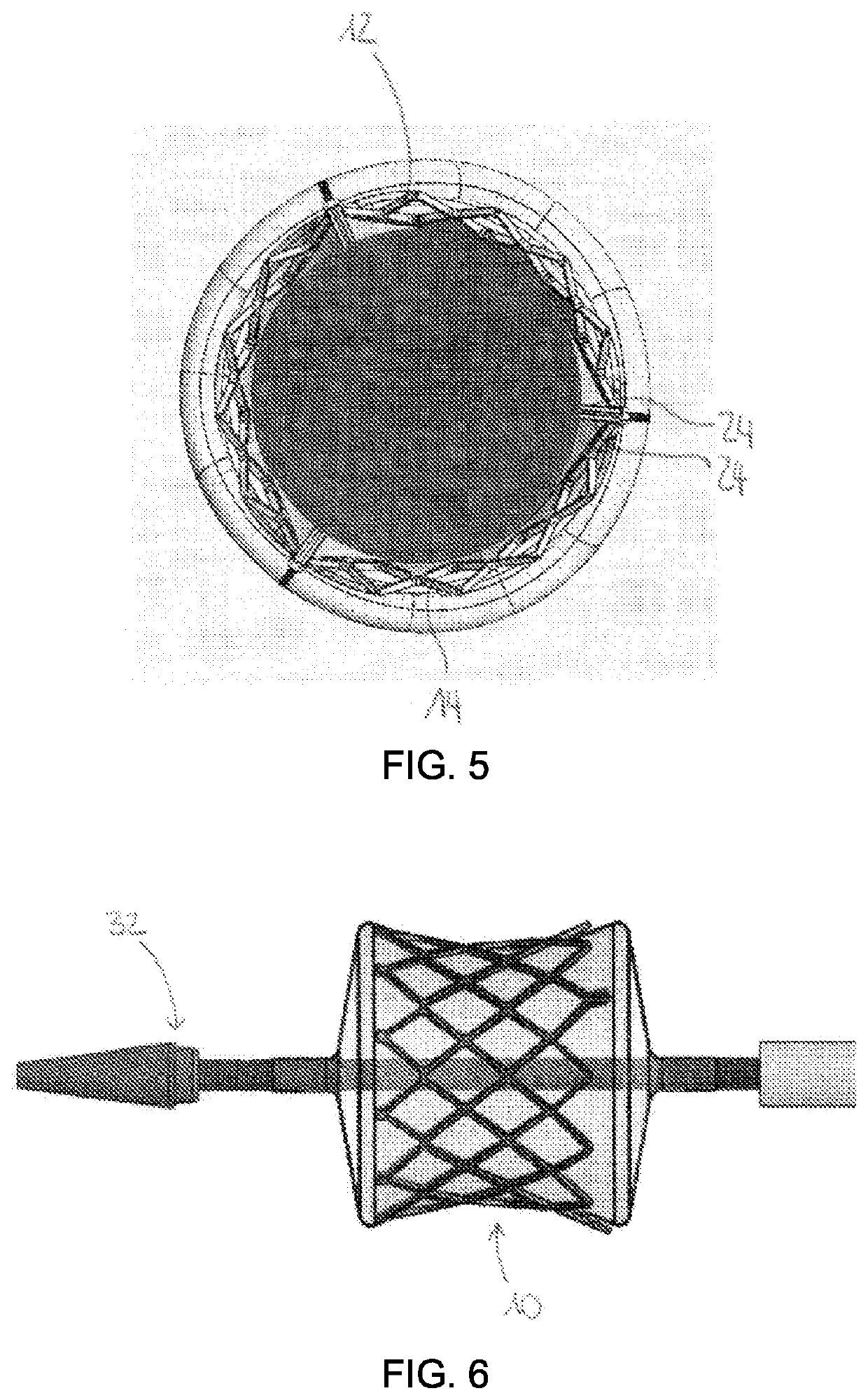
[0089]FIG. 1 shows a perspective view of a stent 10 according to the invention with a stent frame 12 composed of a plurality of arms 14. The stent 10 can be a balloon-expandable or a self-expandable stent 10, both configured to be placed at the aortic artery and the aortic valve of a patient. The stent frame 12 can be composed of Chromium and Cobalt, in the case of a balloon-expandable stent 10, or Nitinol if a self-expandable stent 10 is desired. Both versions of the stent 10 can be delivered in a compressed state to a point of interest such as the aortic artery of a human, where it then can be (self-)expanded once it is deployed.

[0090]The frame 12 further comprises at least two sections, i.e. a proximal section PS and a distal section MS, arranged at a longitudinal axis A. Often the stent further comprises a third section, i.e. a middle section MS, which is arranged between the proximal section PS and the distal section DS respectively. All sections DS, MS, PS are interconnected w...


PUM

PropertyMeasurementUnit
tensile stressaaaaaaaaaa
pHaaaaaaaaaa

Abstract

The invention relates to a stent for placement at an aortic annulus that is expandable from an undeployed state to a deployed state comprising a stent frame having rows of cells with a proximal section and a distal section at a longitudinal axis of the stent, the stent frame being formed by a plurality of arms, the arms being connected to one another at connection points, and wherein the plurality of arms forms a plurality of diamond-shaped stent cells, in particular the rows of cells, formed of vertices at said connection points between the arms, a dry valve made out bovine pericardium arranged at least at the distal section of the stent with the dry bovine pericardium being configured to be rehydrated with a solution, a skirt surrounding the dry valve and comprising at least one of bovine pericardium and polyester, and one or more eyelets arranged at a distal end of some of the arms, with the eyelets being configured to fix the valve to the stent frame.

Description

CROSS REFERENCE TO RELATED APPLICATIONS[0001]This application claims the benefit of foreign priority under 35 U.S.C. § 119 of European patent application number 21157884.4, filed Feb. 18, 2021. The contents of this application are incorporated herein by reference in their entirety.INTRODUCTION[0002]The present invention relates to a stent for placement at an aortic annulus that is expandable from an undeployed state to a deployed state.[0003]A healthy heart facilitates oxygenated blood flow to the extremities. The heart is comprised of two chambers: the right chamber and the left chamber, which manage deoxygenated and oxygenated blood respectively. Deoxygenated blood from the upper and the lower extremities, travels through both caval veins, i.e. the vena cava superior and the vena cava inferior, into the right atrium. It is pumped through the tricuspid valve and into the right ventricle. During systole, when the ventricle is full, the tricuspid valve shuts and blood is pumped from ...

Claims


Application Information

Patent Timeline
Patent Type & Authority Applications(United States)
IPC IPC(8): A61L27/36A61F2/24A61L27/50
CPCA61L27/3625A61F2/2418A61L27/3641A61L27/3687A61L2430/20A61L27/50A61F2220/0025A61L2400/02A61F2/2409A61F2/90A61F2/2412A61F2/2442A61F2/2466A61F2/958A61F2/97A61F2/966A61F2230/0017A61F2220/0008A61F2/2415A61F2250/0039A61L31/005A61L2430/40
Inventor AGRELI, GUILHERMEKISS, KATHARINAEINHELLIG, SIEGFRIED
Owner PF PROD FEATURES GMBH
Why Eureka
Eureka Blog
Learn More