Process for reducing an organic material to produce methane and/or hydrogen

Pending Publication Date: 2022-08-18
HALLETT DOUGLAS JOHN FREDERICK +1
View PDF0 Cites 0 Cited by
  • Summary
  • Abstract
  • Description
  • Claims
  • Application Information

AI Technical Summary

Benefits of technology

This patent describes a process for turning organic material into methane and / or hydrogen gas using a two-step process. The first step involves heating the material with a large amount of hydrogen gas in a chamber without oxygen, at a rapid rate to form a gas mixture containing methane, hydrogen, acid, and partially reduced volatile organic molecules. This gas mixture is then neutralized with a base to produce methane gas. The second step involves heating the gas with a large amount of hydrogen gas to form another gas mixture containing methane, hydrogen, and acid. The technical effect of this patent is a more efficient and effective way to produce methane gas from organic materials.

Problems solved by technology

Another issue with gasification is that large quantities of GHGs are produced from the process and require proper carbon sequestration.
Incineration is very capital intensive, expensive to operate and requires large installations.
Anaerobic digestors have a high initial capital cost as they require large tanks and other process vessels.
Anaerobic digestion also requires long residence times and generally only breaks down the more volatile organic material resulting in diminished gas production and increased residual material compared to other technologies.

Method used


Image

  • Process for reducing an organic material to produce methane and/or hydrogen
  • Process for reducing an organic material to produce methane and/or hydrogen

Examples


example 1

odelling

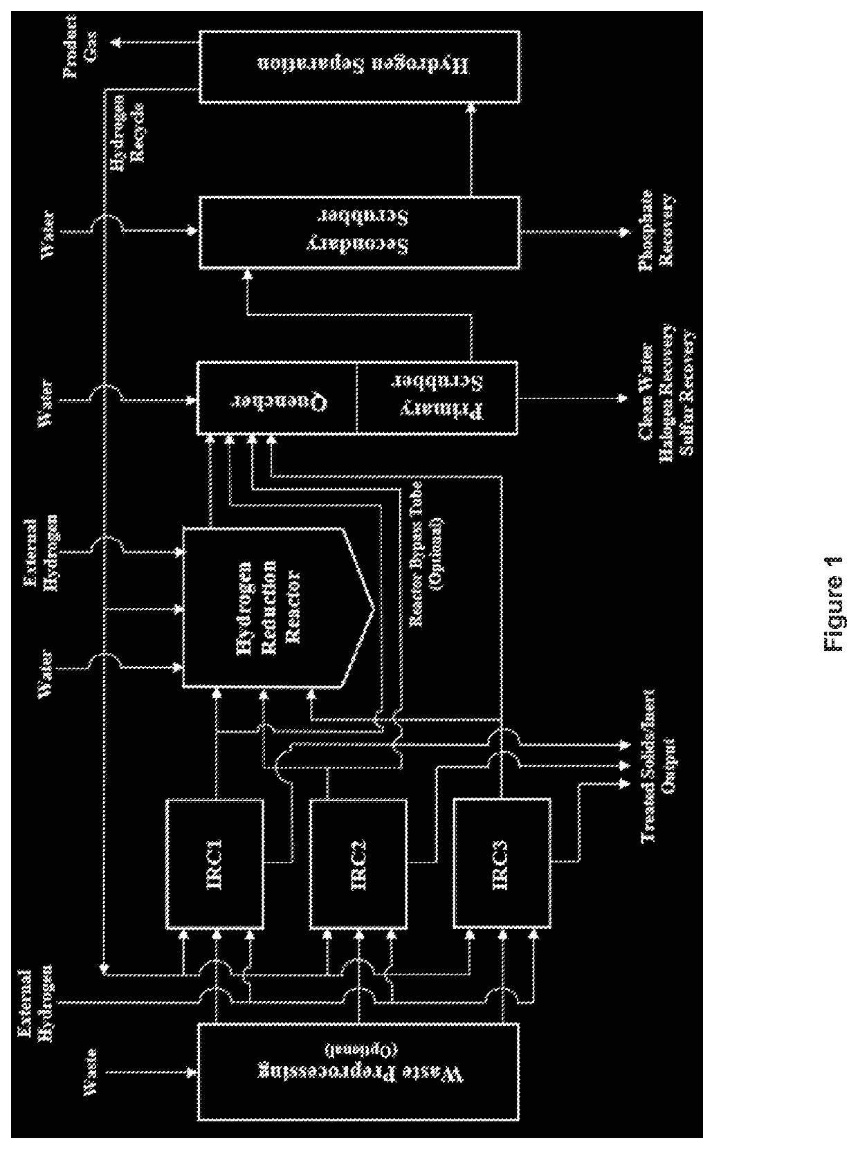
[0170]Two embodiments of the present disclosure are described below to provide examples of the production of methane from the conversion of two specific organic materials. The following examples are based on known chemical compositions of these materials. This information is combined with standard engineering calculations as well as process modeling of the chemical reactions. The chemical reactions have been previously described. The calculations assume that hydrogen is added as a reactant. The following efficiencies for hydrogen separation are used: 85% hydrogen recovery, 92% methane rejection, 100% CO rejection, 50% CO2 rejection, and 100% water rejection.

[0171]In an embodiment, polyethylene-based waste plastic such as Auto Shredder Residue (ASR) is converted to methane or synthetic natural gas (SNG). This material is placed in bins which are placed directly into the Initial Reduction Chambers (IRCs). ASR has the following chemical composition (in mole %) on a dry basis: 2...

example 3

n of Methane from Dry Wood Chips

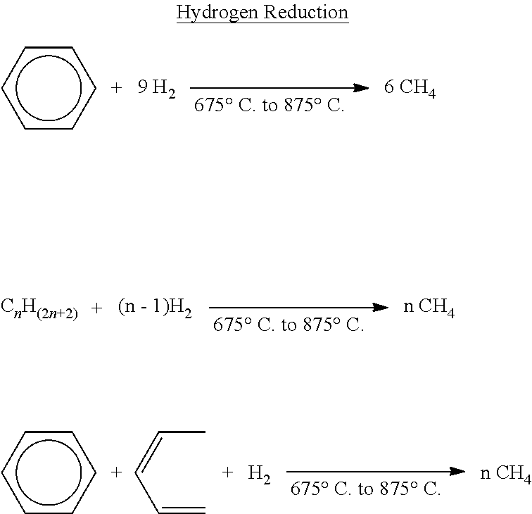
[0175]Example of dry wood chips run following a ramping of the reduction chamber at 8° C. / minute from ambient to 450° C. Containers made with steel mesh were filled with dry wood chips and placed inside a sealed chamber. This chamber was purged of air with nitrogen and placed into an electrically heated oven apparatus. Hydrogen was added at a constant rate and the temperature was ramped at a constant rate of 8° C. / minute to 450° C. at 1 atm pressure. Methane gas began to be detected after the scrubber when the temperature reached 80° C. The concentrations of methane gradually increased as the temperature rose and the concentrations of hydrogen decreased corresponding to the production of methane with the highest concentrations being reached between 400 and 420° C. When 450° C. was reached the ramp rate was stopped since no further methane was being produced. No tar was formed in the scrubber or any other part of the reactor system.


PUM


Abstract

A process for reducing an organic material to produce methane and / or hydrogen is disclosed. The process includes: (a) contacting the organic material with an excess amount of hydrogen gas in an enclosed reduction chamber at ambient temperature, where the reduction chamber is substantially free of oxygen, and heating the reduction chamber to cause a temperature increase in the organic material from ambient temperature to up to 425° C. at a rate of up to about 8° C. per minute, under positive pressure, to form a first gaseous mixture comprising methane, hydrogen, acid, and partially reduced volatile organic molecules; (b) heating the first gaseous mixture to a temperature of about 675° C. to about 875° C. in the presence of an excess amount of hydrogen gas to form a second gaseous mixture comprising methane, hydrogen, and acid; and (c) neutralizing the second gaseous mixture with a base.

Description

FIELD OF THE INVENTION[0001]The present invention pertains to a process for reducing an organic material to produce methane and / or hydrogen. More particularly, the present invention pertains to a process for reducing an organic material to produce methane and / or hydrogen as end product(s), using excess hydrogen under controlled reaction conditions.BACKGROUND[0002]In recent years, many countries and international committees have proposed or issued regulations towards the production of energy from alternative or renewable sources as well as the need to drastically reduce greenhouse gases (GHGs) and other factors which are having an impact on global warming.[0003]In 2014, the United States Environmental Protection Agency (US EPA) developed the “Clean Power Plan” policy aimed at reducing carbon pollution from power plants. Power plants are the largest source of carbon dioxide (CO2) emissions in the United States, accounting for roughly one-third of all domestic greenhouse gas emissions....

Claims


Application Information

Patent Timeline
IPC IPC(8): C01B3/38C01B3/48C10L3/08
CPCC01B3/384C01B3/48C10L3/08C01B2203/0233C01B2203/0405C10L2200/0469C01B2203/067C01B2203/1058C01B2203/1211C01B2203/1258C01B2203/043C10L3/10C01B2203/1076C01B2203/1047C01B2203/1064
Inventor HALLETT, DOUGLAS JOHN FREDERICKWILLIS, DAVID JONATHAN
Owner HALLETT DOUGLAS JOHN FREDERICK
Why Eureka
Try Eureka