There are many practical limitations to the use of the
bus topologies.
The capacitive loading on a
bus due to the attached modules greatly increases the
propagation delay.
In such a transfer the data transfer rate is primarily limited by skews between bits and strobe.
The reflections take one or more bus round trip delays to settle resulting in a
settling time
delay that is a significant portion of the transfer
cycle time for a bus.
These limitations limit the aggregate bandwidth of the FutureBus+ to approx.
In addition to low bandwidths, electronic busses suffer from other limitations.
Finally, electronic busses are not scalable to interconnect hundreds of plug-in modules since the increasing
capacitance,
inductance and impedance problems of a larger bus will lower the already low bandwidth of the bus.
These limitations of electrical busses have not gone unnoticed.
There are number of problems with Balakrishnan's architecture.
The bus is electrical and as a result it will always suffer from
capacitance,
inductance and impedance problems.
Finally, it is not scalable to interconnect hundreds of plug-in modules.
The electronic bus is far too slow to meet the communication demands of a large computing
system.
However, there are many limitations to the electronic interconnects used in current large scale computing and communication networks.
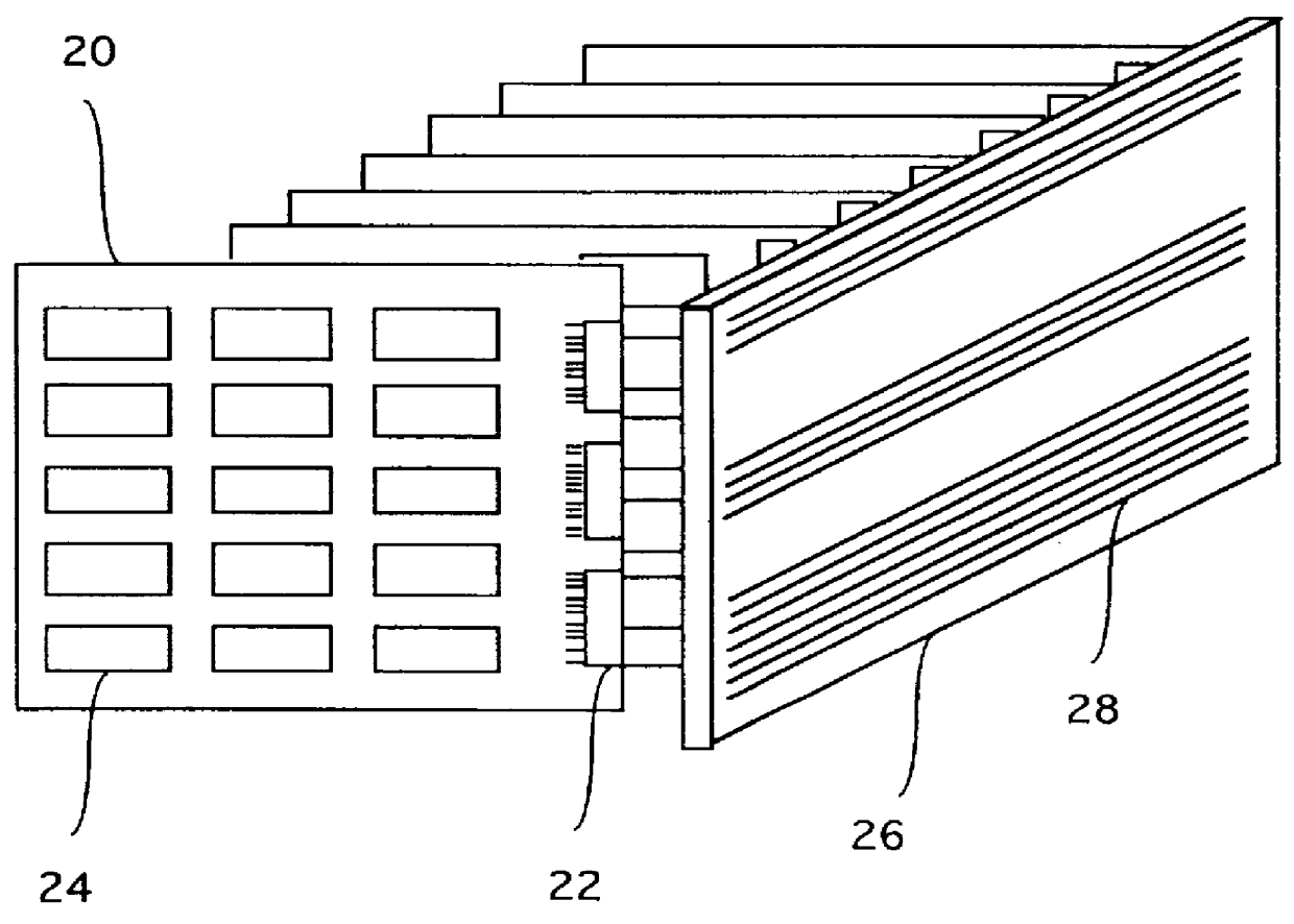
However, the cost of these multiple channels is a large number of electronic wires between cabinets and electronic traces on PCBs.
The
inductance and
capacitance of these wires and traces necessitates the use of high power transceivers which consume large amounts of power.
However, Hamanaka's passive
optical bus still suffers from many disadvantages associated with the electronic bus.
Hamanaka's passive
optical bus does not implement multiple independent optical channels.
The limitation that every PCB must monitor all the data on the
optical bus will limit the rate at which data can be transmitted over the bus to the rate at which every PCB can receive and process the data.
An
integrated circuit (IC) has a limited electronic Input / Output IO bandwidth of typically tens of Gigabits / second due to IC packaging constraints.
Hence, the peak bandwidth of Hamanaka's passive optical bus architecture will be limited to the peak IO bandwidth of an electronic
integrated circuit, typically tens of Gigabits / second.
Hence, Hamanaka's passive optical bus is simply a faster version of a conventional electronic bus and it does not provide the
high bandwidth required by large scale computing and communication systems.
This architecture suffers from the same limitations as Hamanaka's optical bus and a few new limitations.
Their architecture does not support
broadcast channels, it does not support one-to-many communications over a single channel, it does not support one-to-all communications over a single channel, it does not support simultaneous many-to-many communications over multiple channels.
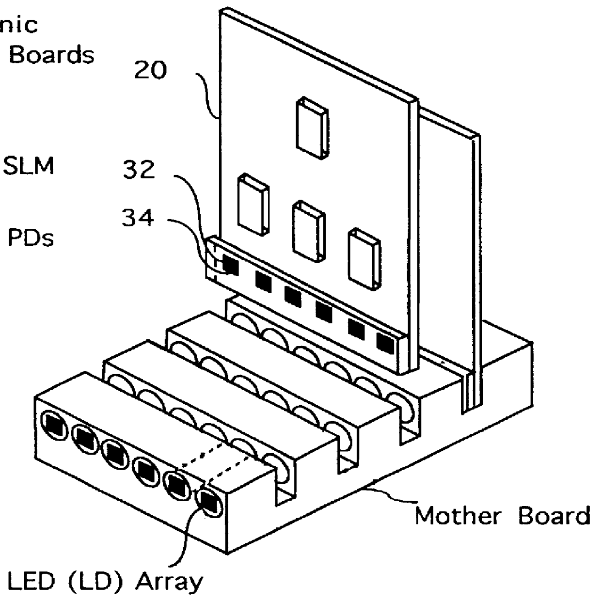
Another key limitation of this architecture is the fact that the optical signals which are received on a
photodetector array must be converted to
electronics and routed off the array
package to an external electronic IC
package for further
processing.
This limitation will limit the peak bandwidth of the optical architecture to the IO bandwidth of a single IC which is typically in the tens of Gbits / sec.
Another key limitation of this architecture is the fact that every individual
laser in the VCSEL
laser array is individually accessible from an IO pin on the VSCEL package.
This limitation also implies that the peak bandwidth of their passive optical interconnect will be equal to the peak IO bandwidth of an IC package: the peak bandwidth is limited to the bandwidth which can be supplied to one VCSEL array package or removed from one
photodetector array package, which is typically in the tens of Gbits / second.
Finally, the architecture will have
optical power limitations as the number of receivers increases.
The architecture does not allow for the regeneration of optical signals.
This technique will allow an optical
signal to be delivered to a small number of receivers, but it cannot be used to interconnect a large number of receivers since the original optical
signal can only pass through a limited number of partially reflective mirrors before the
signal is lost.
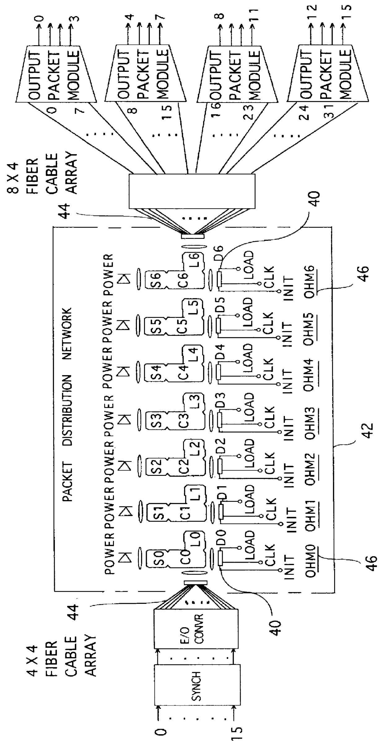
However, the architecture suffers from many disadvantages.
The switch does not allow "locality" between communicating modules i.e., all connections must propagate through all stages of the network .
All communications, even those between modules which are physically close together, must enter the switch at the input side, travel through all the stages of devices and exit the switch at the output side, which can require excessive amounts of time.
In a large
system the length of
fiber just to get data to the input side can cause excessive delays and similarly for the output side.
Furthermore, this switch architecture does not support plug-in modules or data transfers between neighboring plug-in modules.
A literature and
patent search did not reveal any prior art in reconfigurable intelligent optical backplanes.
Batch fabrication of a large number of such identical devices will lower the per
unit cost significantly, since the custom fabrication of individual devices is not cost effective.

