Process for treating H.sub.2 S containing streams

a technology of h.sub.2 and stream, which is applied in the field of improving the process for the conversion of h.sub.2 s to sulfur, can solve the problems of severe endotherms and arisen problems involving endotherms, and achieve the effect of increasing the load on the sorben

Inactive Publication Date: 2000-02-29
MOBIL OIL CORP
View PDF9 Cites 35 Cited by
  • Summary
  • Abstract
  • Description
  • Claims
  • Application Information

AI Technical Summary

Benefits of technology

Further advantages of the precombustion scheme described here are that the effluent from the combustion can be supplied at high temperature (approx. 2000-2500.degree. F.). When mixed with the main flow of modestly preheated feed, a temperature of around 1200.degree. F., as required for effective regeneration of the sorbent bed, can be obtained. Furthermore, the total gas flow through the "sulfated" bed is increased, which can help supply heat for the endothermic desorption process. The effective concentration of the reducing H.sub.2 S (H.sub.2 S remaining after reaction with SO.sub.2) is decreased, which should also help in combating endotherms in the sorbent bed.
Because the reaction of H.sub.2 S and SO.sub.2 is typically equilibrium limited, and this equilibrium is particularly unfavorable at the preferred MOST temperatures of 1100-1200.degree. F., it is likely that some unconverted H.sub.2 S and SO.sub.2 will break through the initial "sulfated" sorbent bed. These sulfur species will be converted to SOx in the main burner, and sorbed on the final MOST sorbent bed, increasing the load on the sorbent.

Problems solved by technology

In some cases the endotherm may be so severe that it cools the bed off and shuts down the regeneration before it is complete.
Problems involving endotherms arise more often if a low flow of highly concentrated H.sub.2 S is used, rather than a dilute stream.

Method used


Image

  • Process for treating H.sub.2 S containing streams
  • Process for treating H.sub.2 S containing streams
  • Process for treating H.sub.2 S containing streams

Examples


Embodiment Construction

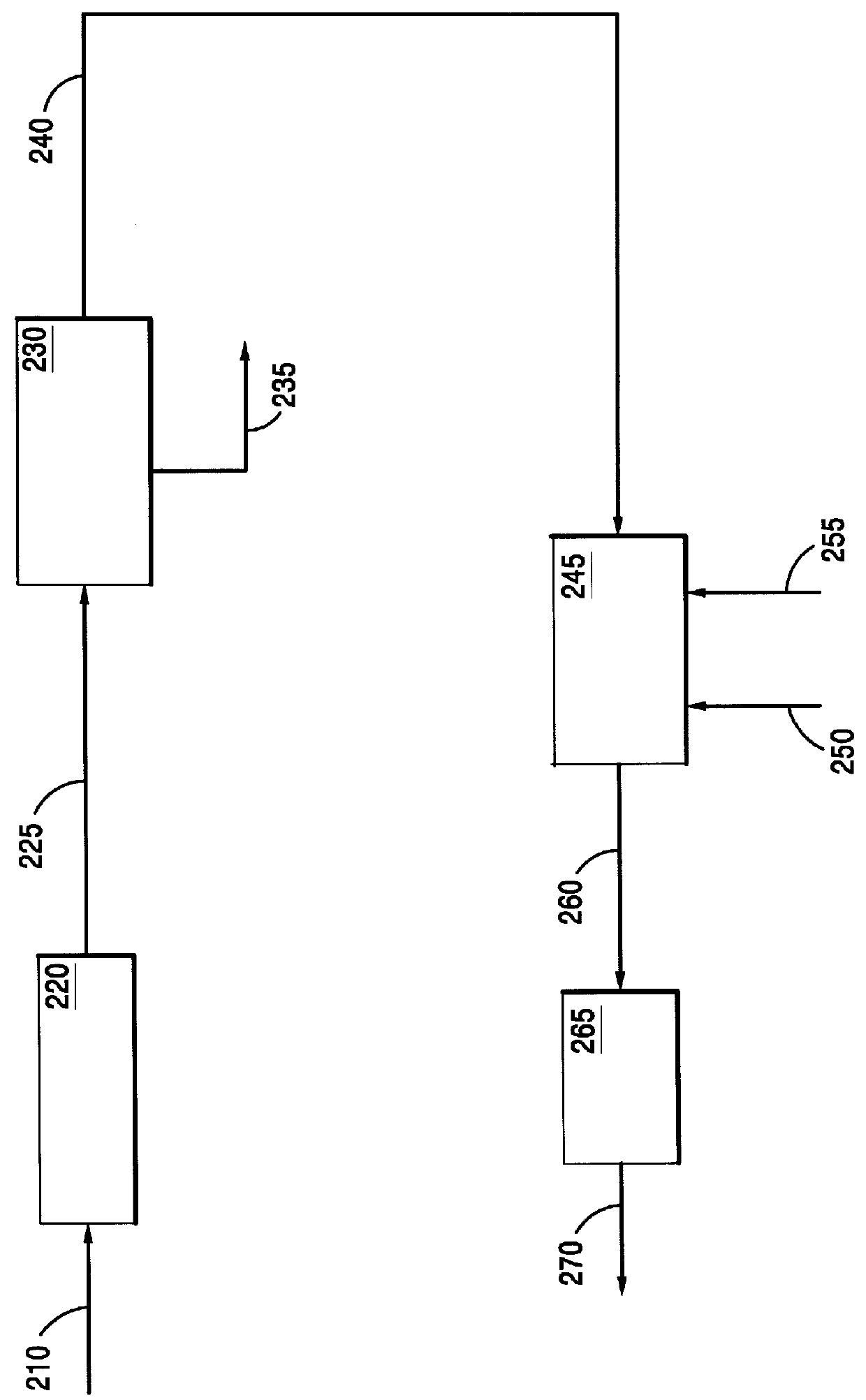
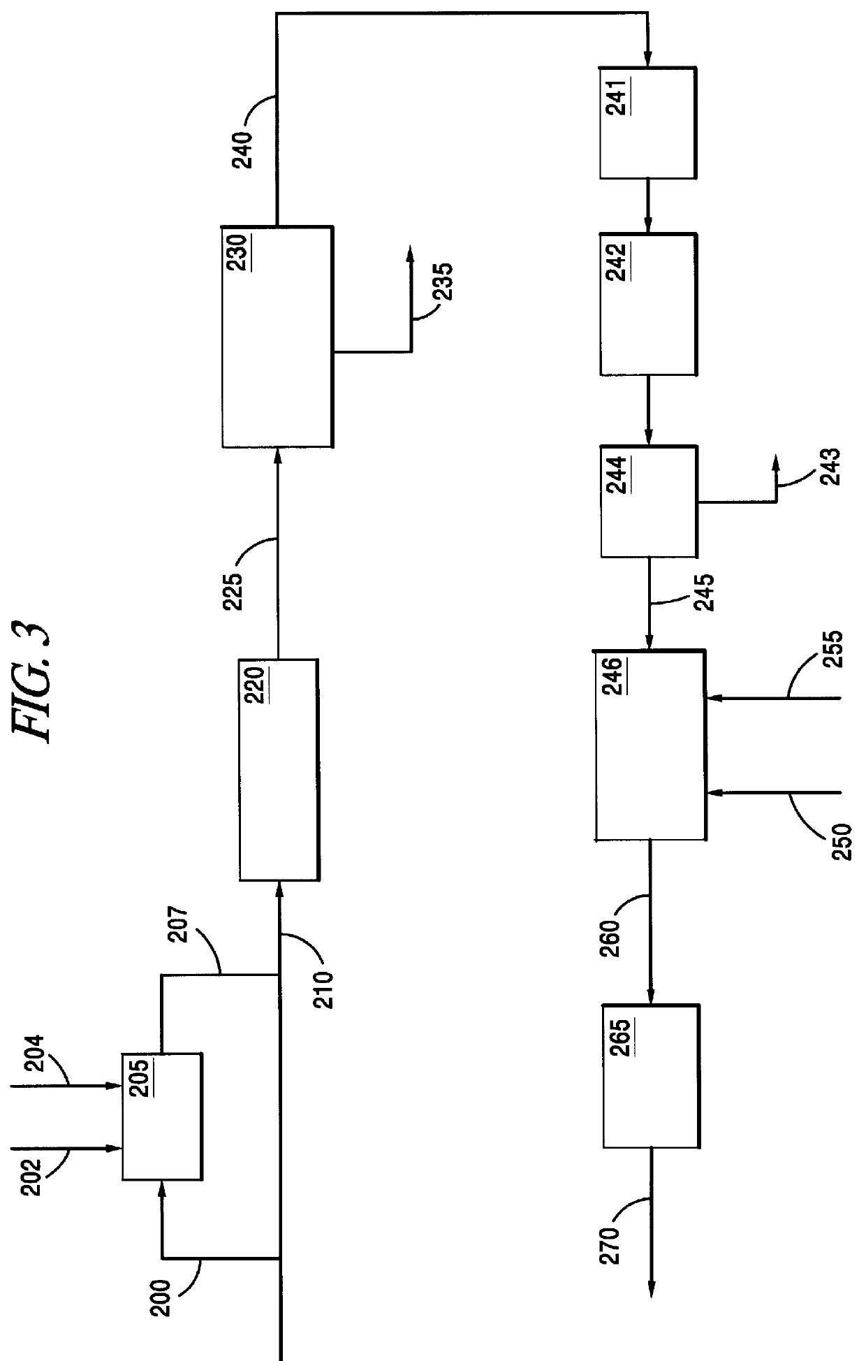
This invention relates to a process for the direct conversion of hydrogen sulfide to elemental sulfur. This solid oxide based process is useful to replace or use in conjunction with a Claus plant, a Claus tail gas unit and an acid gas enricher. A typical hydrogen sulfide conversion process includes the use of a hydrogen sulfide gathering system, such as a solvent (e.g. amine) absorber / stripper system, followed by a Claus plant, which is in turn followed by a Claus tail gas unit. In some cases, such as where carbon dioxide, and possibly other sulfur species, are present, and the hydrogen sulfide is available in low concentrations, the initial hydrogen sulfide gathering system is frequently followed by a second hydrogen sulfide gathering system or an acid gas enricher, such as a Flexsorb.TM. amine absorber / stripper system. As mentioned above, the process of the instant invention converts hydrogen sulfide directly to elemental sulfur by contacting the hydrogen sulfide with a sulfated c...


PUM

PropertyMeasurementUnit
temperatureaaaaaaaaaa
temperaturesaaaaaaaaaa

Abstract

This invention is directed to an improved process for conversion of H2S to sulfur, using MOST(Mobil Offgas Sulfur Treatment) catalyst or sorbent. The sorbent is typically a magnesium-aluminate spinet, with oxidation promoters such as ceria and vanadia. H.sub.2 S from the feed gas is used to regenerate sulfated sorbent, simultaneously producing elemental sulfur which is then condensed out. The improvement involves combusting part of the feed, converting some of the feed H.sub.2 S to SO.sub.2 prior to contacting the sulfated sorbent. Thus much of the stoichiometric oxygen required for conversion of H.sub.2 S to S is supplied in the form of SO.sub.2 by this pre-combustion step, instead of coming totally from the oxidized/sulfated solid sorbent. This can decrease the amount of sorbent required, as well as the frequency of regenerations, thus reducing process cost. The hot combustion gas also helps to heat the feed stream. One or more Claus reactors may optionally be added, to further increase sulfur recovery efficiency.

Description

FIELD OF THE INVENTIONThis invention concerns an improved process for conversion of H.sub.2 S to sulfur, using a sulfated MOST(Mobil Offgas Sulfur Treatment or Mobil Oil SOx Treatment) type catalyst or sorbent. The sorbent is typically a magnesium-aluminate spinel, with oxidation promoters such as ceria and vanadia. The improvement consists of combusting part of the feed, converting some of the feed H.sub.2 S to SO.sub.2 prior to contacting the sulfated sorbent. Thus, much of the stoichiometric oxygen required for conversion of H.sub.2 S to S is supplied in the form of SO.sub.2 by this pre-combustion step, instead of all coming from the oxidized and sulfated solid sorbent. This can significantly decrease the amount of sorbent required, as well as the frequency of regenerations, thus reducing process cost. Optionally, one or more Claus reactors may be added to further increase sulfur recovery efficiency.BACKGROUND OF THE INVENTIONIn a number of processes, such as the refining of crud...

Claims


Application Information

Patent Timeline
Patent Type & Authority Patents(United States)
IPC IPC(8): B01J20/08B01J20/06B01J20/04B01D53/48B01D53/52B01J20/28C01B17/04C01B17/00
CPCB01D53/523B01J20/06B01J20/08B01J20/28014B01J20/3458B01J20/041B01J20/3433C01B17/0404Y10S502/514
Inventor BUCHANAN, JOHN S.NARIMAN, KHUSHRAV E.
Owner MOBIL OIL CORP
Why Eureka
Try Eureka