Method for making a lithographic printing plate involving on press development

Inactive Publication Date: 2000-02-29
EASTMAN KODAK CO
View PDF6 Cites 121 Cited by
  • Summary
  • Abstract
  • Description
  • Claims
  • Application Information

AI Technical Summary

Benefits of technology

It is an object of the present invention to provide a method for making a printing pla

Problems solved by technology

Lithography is the process of printing from specially prepared surfaces, some areas of which are capable of accepting lithographic ink, whereas other areas, when moistened with water, will not accept the ink.
However, such method most often results in poor lithographic preformance so that in practice a Developer Desensitizer is almost always needed.
A particular disadvantage of photosensitive imaging elements such as described above for making a printing plate is that they have to be shielded from the light.
This is a particular disadvantage if on press development is contemplated since mounting the

Method used


Image

  • Method for making a lithographic printing plate involving on press development
  • Method for making a lithographic printing plate involving on press development
  • Method for making a lithographic printing plate involving on press development

Examples


second embodiment

A light to heat converting compound in connection with the present invention is most preferably added to the image forming layer but at least part of the light to heat converting compound may also be comprised in a neighbouring layer. Such layer can be for example the cross-linked hydrophilic layer of a lithographic base according to lithographic bases explained above.

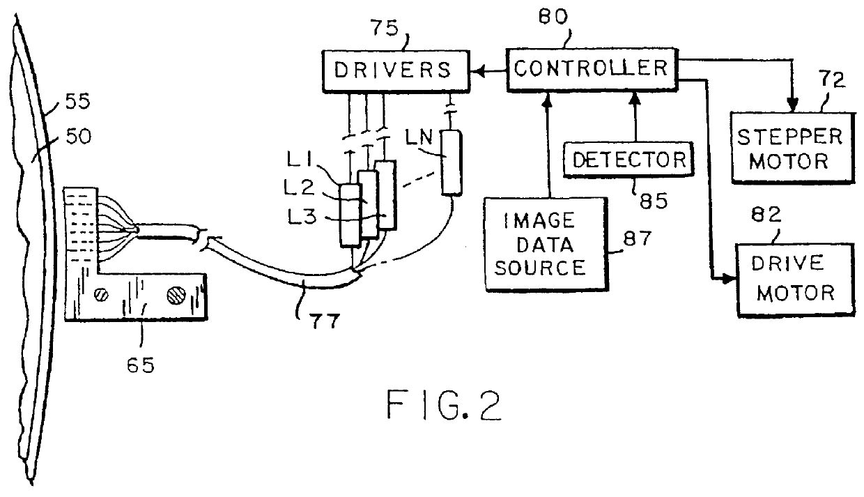
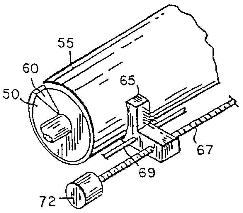
In accordance with a method of the present invention for obtaining a printing plate, the imaging element is image-wise exposed and subsequently is mounted on a print cylinder of a printing press. According to a preferred embodiment, the printing press is then started and while the print cylinder with the imaging element mounted thereon rotates, the dampener rollers that supply dampening liquid are dropped on the imaging element and subsequent thereto the ink rollers are dropped. Generally, after about 10 revolutions of the print cylinder the first clear and useful prints are obtained.

According to an alternative method,...

example 1

Preparation of a Lithographic Base

A 0.2 mm thick aluminium foil was degreased by immersing the foil in an aqueous solution containing 5 g / l of sodium hydroxide at 50.degree. C. and rinsed with demineralised water. The foil was then electrochemically grained using an alternating current in an aqueous solution containing 4 g / l of hydrochloric acid, 4 g / l of hydroboric acid and 0.5 g / l of aluminium ions at a temperature of 35.degree. C. and a current density of 1200 A / m.sup.2 to form a surface topography with an average center-line roughness R.sub.a of 0.5 .mu.m.

After rinsing with demineralised water the aluminium foil was then etched with an aqueous solution containing 300 g / l of sulfuric acid ate 60.degree. C. for 180 seconds and rinsed with demineralised water at 25.degree. C. for 30 seconds.

The foil was subsequently subjected to anodic oxidation in an aqueous solution containing 200 g / l of sulfuric acid at at temperature of 45.degree. C., a voltage of about 10 V and a current densi...

example 2

An imaging element was prepared as described in example 1 with the exception that the submersion of the lithographic base in a citric acid solution was omitted and the lithographic base was directly coated with the coating composition.

A printing plate was prepared as in example 1 and after a total of 20 revolutions of the print cylinder, clear prints were obtained without ink uptake in the non-image areas.


PUM

PropertyMeasurementUnit
Angleaaaaaaaaaa
Temperatureaaaaaaaaaa
Flexibilityaaaaaaaaaa

Abstract

The present invention provides a method for making a lithographic printing plate comprising the steps of: (1) image-wise exposing to light an imaging element comprising (i) on a hydrophilic surface of a lithographic base an image forming layer comprising hydrophobic thermoplastic polymer particles capable of coalescing under the influence of heat and dispersed in a hydrophilic binder and (ii) a compound capable of converting light to heat, said compound being comprised in said image forming layer or a layer adjacent thereto; (2) and developing a thus obtained image-wise exposed imaging element by mounting it on a print cylinder of a printing press and supplying an aqueous dampening liquid and/or ink to said image forming layer while rotating said print cylinder.

Description

DESCRIPTION1. Field of the Invention.The present invention relates to a method for making a lithographic printing plate. More in particular, the present invention relates to a method wherein the lithographic printing plate is developed on the printing press subsequent to image-wise exposure.2. Background of the InventionLithography is the process of printing from specially prepared surfaces, some areas of which are capable of accepting lithographic ink, whereas other areas, when moistened with water, will not accept the ink. The areas which accept ink form the printing image areas and the ink-rejecting areas form the background areas.In the art of photolithography, a photographic material is made imagewise receptive to oily or greasy inks in the photo-exposed (negative-working) or in the non-exposed areas (positive-working) on a hydrophilic background.In the production of common lithographic printing plates, also called surface litho plates or planographic printing plates, a support...

Claims


Application Information

Patent Timeline
IPC IPC(8): B41C1/10B41M5/36
CPCB41C1/1025B41M5/366B41C2201/04B41C2201/14B41C2210/04B41C2210/08B41C2210/24
Inventor VERMEERSCH, JOANVAN DAMME, MARC
Owner EASTMAN KODAK CO
Why Eureka
Try Eureka