Process for the thermo-hydraulic control of gas hydrates

a technology of thermohydraulic control and gas hydrate, which is applied in the direction of insulation, sealing/packing, and wellbore/well accessories, etc., can solve the problems of incomplete plugging of production flow, huge drawbacks of well infectivity, and insufficient cohesion forces between host and guest molecules to form clathrates

Inactive Publication Date: 2000-03-14
PETROLEO BRASILEIRO SA (PETROBRAS)
View PDF17 Cites 102 Cited by
  • Summary
  • Abstract
  • Description
  • Claims
  • Application Information

AI Technical Summary

Benefits of technology

The present invention provides further for a Nitrogen Generating System for preventing the formation of gas hydrates during water injection in subsea wells.

Problems solved by technology

Due to geometrical reasons, such components cannot abandon the network of water molecules linked by hydrogen bridges until such network collapses.
However the cohesion forces between the host and guest molecules do not suffice for forming a clathrate.
When the gas hydrate deposits are found in the production string or even in the surgency line, such deposits invariably cause the complete plugging of the production flow.
Under conditions of secondary recovery such as the method known as Water Alternating Gas (WAG) where water and gas are alternatively pumped into a reservoir through an injection well under conditions of low temperature and high pressure, the water-as mixture may form hydrates which can plug the injection well, bringing huge drawbacks to the well infectivity.
Also, under conditions of petroleum oil production, there are situations where the gas produced in the presence of cold water creates conditions of gas hydrate formation, which may plug the wet gas streamflow.
Still, the transportation of petroleum fluids along pipelines or lines from offshore equipments to shore facilities may generate conditions for the formation of gas hydrates, the flow of fluid throughout the pipeline or line being thus impaired.
However, the control of gas hydrate formation by means of additives may be costly and of reduced efficacy.

Method used


Image

  • Process for the thermo-hydraulic control of gas hydrates
  • Process for the thermo-hydraulic control of gas hydrates
  • Process for the thermo-hydraulic control of gas hydrates

Examples


Embodiment Construction

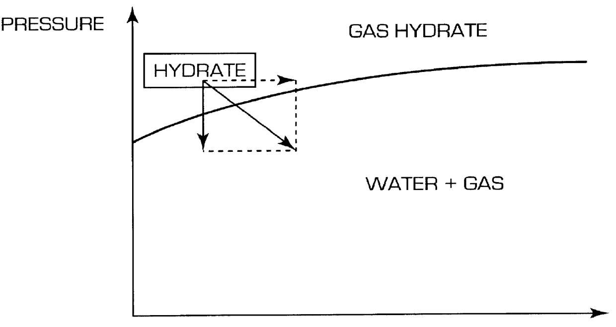
In the present specification, the expression "gas hydrate control" means either the dissolution of the gas hydrate plugs already formed or the prevention of their formation.

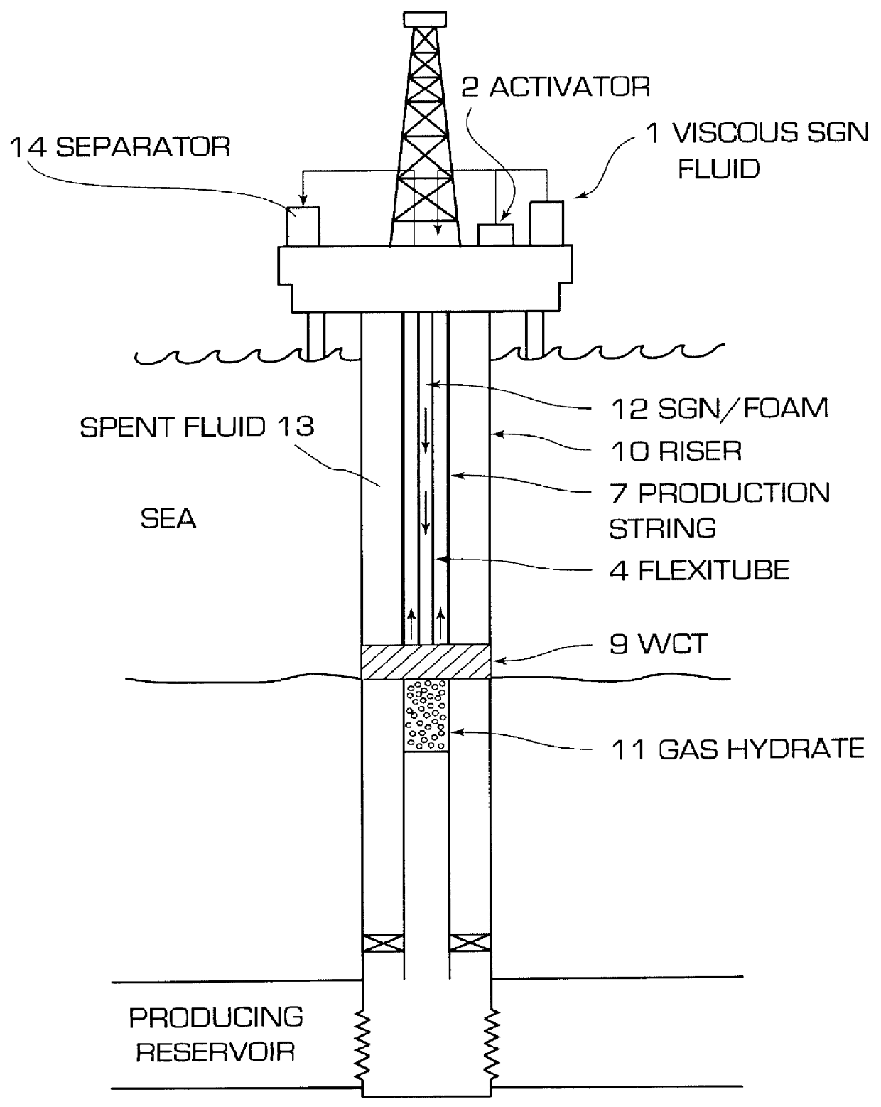
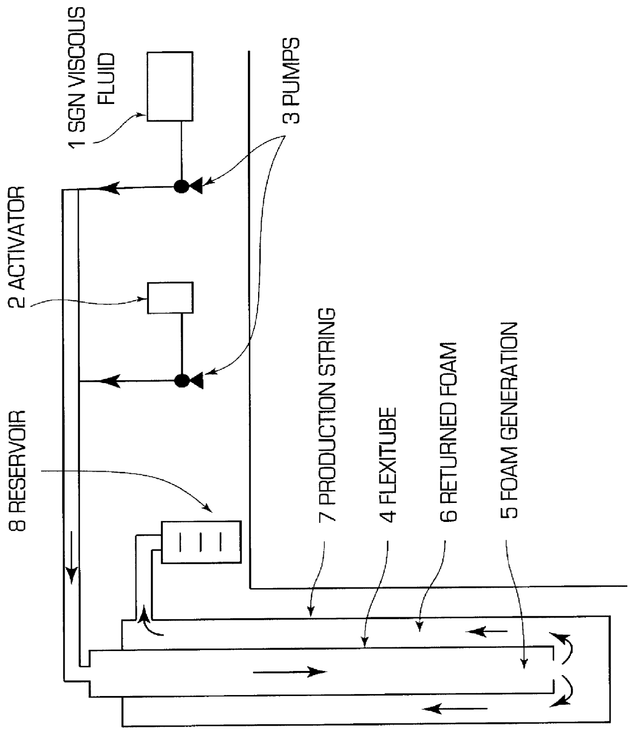
According to the SGN method, the nitrogen and heat generation is effected by the reaction of nitrite and ammonium ions present in an aqueous solution of these salts, from which are obtained nitrogen gas and heat. The nitrogen- and heat-generating aqueous solution contains: a) a compound which contains at least one atom of nitrogen to which is linked at least one hydrogen atom, such compound being able of being quick and exothermically oxidized, in an acid aqueous solution, so as to yield heat, nitrogen gas and by-products which are liquid or dissolved, while substantially inert to the well or to any equipment which these products may be contacted; b) at least one oxidizing agent able to oxidize the nitrogen compound of a); c) a buffer system able to keep the solution pH at a level around 5.0 or less. Such as appl...


PUM

PropertyMeasurementUnit
boiling pointaaaaaaaaaa
volume %aaaaaaaaaa
volume %aaaaaaaaaa

Abstract

A process for the thermo-hydraulic control of gas hydrates in subsea production and injection wells as well as pipelines which transport liquid or gaseous hydrocarbons is described, the process making use of a Nitrogen Generating System foamed or in solution. The control may signify the prevention of the formation of the gas hydrates or the dissolution of the gas hydrate plug already formed. Under conditions of use designed for the prevention of the formation of gas hydrates the SGN fluid prevents the thermal conditions leading to the gas hydrate plugs. Under conditions of use designed to dissolve the already formed gas hydrate plugs, the SGN fluid alters the thermo-hydraulic conditions which favor the gas hydrate plugs, so that they are dissolved and return to the water+gas phase.

Description

The present invention relates to a process for the thermo-hydraulic control of gas hydrates with the aid of a Nitrogen Generating System (also known as "SGN", based on the Portugese "Systema Gerador de Nitrogenio"). More specifically, the present invention relates to a process for the thermo-hydraulic control of gas hydrates of any low boiling hydrocarbon stream in the presence of humidity so that the thermo-hydraulic conditions lead to the formation of such gas hydrates, the process being carried out with the aid of Nitrogen Generating System (SGN).BACKGROUND INFORMATIONGas hydrates are formed whenever water and hydrocarbon gases are combined under high pressure and low temperature.Gas hydrates are crystal lattices made up of two or more constituents. The molecules of one component (always water) form a structure having relatively large cavities, which are occupied by the molecules of other constituents, these being separate gases or gaseous mixtures.Gases which are important from ...

Claims


Application Information

Patent Timeline
Patent Type & Authority Patents(United States)
IPC IPC(8): C09K8/52E21B43/32
CPCC09K8/52C09K2208/22Y10S585/95Y10S507/927Y10T137/0391
Inventor KHALIL, CARLOS NAGIBROCHA, NELSON DE OLIVEIRALEITE, LUCIA CRISTINA FERREIRA
Owner PETROLEO BRASILEIRO SA (PETROBRAS)
Why Eureka
Try Eureka