Method and apparatus for manufacturing disc-shaped recording medium

a technology of disc-shaped recording medium and manufacturing method, which is applied in the direction of manufacturing tools, light beam reproducing, instruments, etc., can solve the problems of inability to ensure the uniform thickness of protective film, inability to prevent corrosion of the recording layer of the magneto-optical disc, and inability to generate an excessively strong magnetic field across the magnetic head

Inactive Publication Date: 2000-06-20
SONY CORP
View PDF8 Cites 58 Cited by
  • Summary
  • Abstract
  • Description
  • Claims
  • Application Information

AI Technical Summary

Benefits of technology

It should be noted that if, in the method and apparatus for manufacturing the disc-shaped recording medium according to the present invention, the disc-shaped recording medium as the material for coating is such a recording medium in which the groove is formed on a radially inner side with respect to the recording area adapted for recording the information, the outer diameter of the disc portion stopping up the center opening is larger than the outer diameter of the groove. If the outer diameter of the disc portion stopping up the center opening is larger than the outer diameter of the groove, the coating liquid can be prevented from entering the groove. Meanwhile, this groove is formed by transcription to the substrate of the profile of a retention member used for securing the stamper for molding a substrate.
The method and apparatus for manufacturing the disc-shaped recording medium according to the present invention are applied when forming a protective film used for protecting e.g., the recording layer of the disc-shaped recording medium. In particular, the present method and apparatus for manufacturing the disc-shaped recording medium are effective for forming a protective film for the disc-shaped recording medium in which the information is recorded and / or reproduced on illumination of the laser light from the side of the protective film. In the case of the disc-shaped recording medium in which the laser light is illuminated from the side of the protective film, it is required strongly to suppress the variation in the film thickness of the protective film. Thus, the present method and apparatus for manufacturing the disc-shaped recording medium, capable of suppressing the variation in film thickness of the coating film, is particularly suited for forming the protective film for this type of the disc-shaped recording medium.
It should be noted that if, in the method and apparatus for manufacturing the disc-shaped recording medium according to the present invention, the disc-shaped recording medium as the material for coating is such a recording medium in which the groove is formed on a radially inner side with respect to the recording area adapted for recording the information, the outer diameter of the disc portion stopping up the center opening is larger than the outer diameter of the groove. If the outer diameter of the disc portion stopping up the center opening is larger than the outer diameter of the groove, the coating liquid can be prevented from entering the groove. Meanwhile, this groove is formed by transcription to the substrate of the profile of a retention member used for securing the stamper for molding a substrate.
Also, if, when dismounting the rotary disc from the turntable, a gas is ejected to a space between the disc portion of the rotary disc unit and the disc-shaped recording medium, in accordance with the present invention, the coating liquid can be prevented form being intruded into a space between the disc unit and the disc-shaped recording medium. Thus, if the coating film forming operation is repeated on different disc-shaped recording mediums, the coating film can be formed without contaminating the disc portion or the disc-shaped recording medium.
Moreover, if at least the bottom side of the recess of the rotary shaft portion is formed of magnetic metal, and at least the distal end of the center shaft of the rotary disc unit is formed by a magnet, the center shaft of the rotary disc unit can be strongly fitted in the recess of the rotary shaft portion. Thus, the coating film can be formed in stability without producing vibrations of the center shaft of the rotary disc unit.
In addition, if the coil is mounted on the rotary disc unit and the electromagnet is constituted by the magnetic metal portion of the rotary shaft and the coil, the center shaft of the rotary disc unit can be mounted on or dismounted from the recess of the rotary shaft portion by the magnetic force produced by adjusting the direction of the magnetic field from the magnet. Further, if the magnetic field opposite in direction to the magnetic field of the magnet on the center shaft of the rotary disc unit, the center shaft of the rotary disc unit can be easily mounted on or dismounted from the recess of the rotary shaft portion. If the current is allowed to flow in the coil of the electromagnet to produce a magnetic field opposite in direction to that of the magnet of the center shaft of the rotary disc unit, the center shaft of the rotary disc unit can be easily mounted on or dismounted from the recess of the rotary shaft portion.

Problems solved by technology

Since the magnetic field needs to be inverted at an elevated speed during signal recording, it is not possible to generate an excessively strong magnetic field across the magnetic head used for recording in the magnetic field modulating system.
However, if the protective film is formed as shown in FIG. 1, it is difficult to assure a uniform thickness of the protective film over the entire surface of the disc substrate, even if the operating conditions during application of the protective coating material are adjusted, such that the film thickness on the outer rim of the disc substrate 1 is thicker than that on its inner rim.
However, if the film thickness of the protective film is reduced excessively, it becomes impossible to prevent corrosion of the recording layer of the magneto-optical disc.
If the wavefront aberration is produced in an optical head due to film thickness difference of the protective film, the laser light illuminated on the recording layer is unstable to deteriorate the recording / reproducing characteristics.
However, if, when there is a film thickness error of the order of approximately 5 .mu.m in the above-described protective film, the optical system of the short wavelength and the high numerical aperture is used, the wavefront aberration W.sub.4od calculated from the equation 1 is of a larger value, such that stable recording / reproduction cannot be realized.
However, it has not been possible with this method to eliminate the variation in the film thickness of the protective film completely such that there is produced a small film thickness difference between the inner and outer rims of the disc.
In the case of the disc-shaped recording medium having a center opening, the coating liquid cannot be supplied to the center of rotation.
However, if simply the center opening of the disc-shaped recording medium is stopped by a rotary disc, it is feared that the coating liquid is intruded into the space between the rotary disc and the disc-shaped recording medium by the capillary phenomenon.

Method used


Image

  • Method and apparatus for manufacturing disc-shaped recording medium
  • Method and apparatus for manufacturing disc-shaped recording medium
  • Method and apparatus for manufacturing disc-shaped recording medium

Examples


first embodiment

A magneto-optical disc 1 manufactured in the present embodiment is a magneto-optical disc for recording / reproduction in accordance with the magnetic field modulation system. Referring to FIG. 5, a recording layer 3 is formed on a disc substrate 2 and a protective film 4 for protecting the recording layer 3 is formed on the recording layer 3.

During recording / reproduction, an optical head 5 and a magnetic head 6 are arranged on the side of the disc substrate 2 and on the side of the protective film 4 of the magneto-optical disc 1, respectively. During recording of information signals, a laser light beam is illuminated from the side of the disc substrate 2 by the optical head 2, at the same time as a magnetic field modulated in accordance with recording information signals is applied by the magnetic head 6 from the side of the protective film 4.

In this magneto-optical disc 1, the disc substrate 2 os a disc-shaped transparent substrate having a thickness of a few mm. The disc substrate ...

second embodiment

A second embodiment of a disc-shaped recording medium according to the present invention is hereinafter explained.

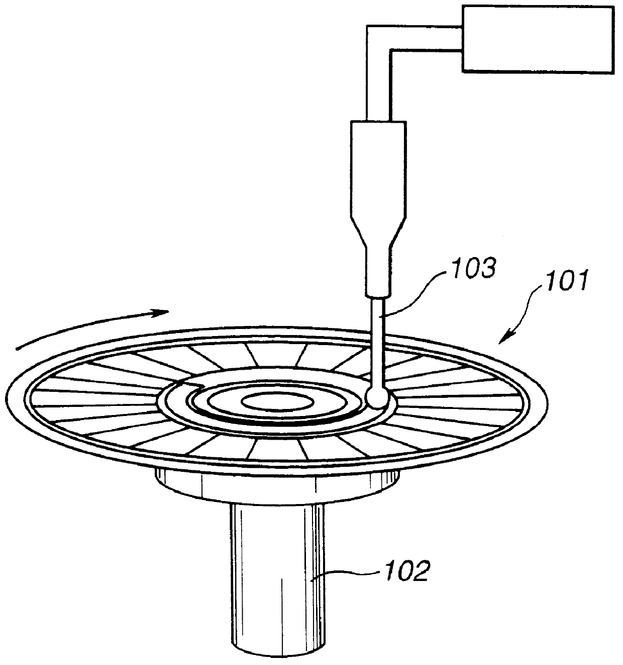
Referring to FIGS. 5 to 7, a manufacturing device for the disc-shaped recording medium includes a rotary shaft portion 31 having, on its one end 31a, a flange 33 of a substantially toroidal planar configuration having an end 31a supporting a disc substrate 32 of a disc-shaped recording medium. The rotary shaft portion 31 has a center recess 34 opened in the end 31a. The manufacturing device for the disc-shaped recording medium also includes a rotary disc unit 38 having a disc portion 36 covering a center opening 35 of a disc substrate 32 of the disc-shaped recording medium and a center shaft 37 fitted in the recess 34 of the rotary shaft portion 31.

The rotary shaft portion 31 is substantially columnar in profile and has the flange 33 on its end 31a. The flange 33 is not provided at the distal end of the end 31a but is slightly recessed such that a projection 51 is formed...


PUM

PropertyMeasurementUnit
thicknessaaaaaaaaaa
thicknessaaaaaaaaaa
thicknessaaaaaaaaaa

Abstract

When applying a coating film by a spin coating method on a disc-shaped recording medium, the film thickness difference between the inner rim and the outer rim of the disc has to be suppressed. To this end, a coating liquid is supplied to a center portion of the disc-shaped recording medium and a rotary disc, as a center shaft of a rotary disc is inserted into a recess formed in a turntable on which the disc-shaped recording medium is set and the disc-shaped recording medium and a rotary disc are run in rotation. The coating liquid is spread under the centrifugal force caused by rotation for forming a coating film on the disc-shaped recording medium.

Description

1. Field of the InventionThis invention relates to a method and apparatus for manufacturing a disc-shaped recording medium, such as a magneto-optical disc. More particularly, it relates to a method and apparatus for applying a coating liquid, such as a material for a protective film, on a disc-shaped recording medium.2. Description of Related ArtThe photomagnetic recording system is such a system in which a recording layer of a magnetic material is locally heated on light irradiation to a temperature higher than the Curie temperature or temperature compensation point to reduce the coercivity in this portion and in which a recording magnetic field is applied to this portion from outside to change partially the direction of magnetization of the recording layer to record information signals. This photomagnetic recording system is finding practical use in an optical filing system, an external storage device for a computer or in a recording device for the audio and video information.Amon...

Claims


Application Information

Patent Timeline
Patent Type & Authority Patents(United States)
IPC IPC(8): B05C11/08B29D17/00G11B11/105G11B11/00G11B7/26B05D1/00
CPCB05C11/08G11B7/26G11B11/10582B29D17/005B05D1/005Y10S425/81
Inventor KIKUCHI, MINORU
Owner SONY CORP
Why Eureka
Try Eureka