Gas engine with a gas fuel reforming device

a technology of gas fuel reforming device and gas engine, which is applied in the direction of engine components, machines/engines, mechanical equipment, etc., can solve the problem of large loss

Inactive Publication Date: 2000-06-27
ISUZU MOTORS LTD
View PDF15 Cites 75 Cited by
  • Summary
  • Abstract
  • Description
  • Claims
  • Application Information

AI Technical Summary

Benefits of technology

The CO.sub.2 dissolving device dissolves CO.sub.2 of the exhaust gas in a solvent to form a solution and releases N.sub.2 and H.sub.2 O (water vapor at 100.degree. C. or higher) of the exhaust gas out into the atmosphere. Hence, only N.sub.2 and H.sub.2 O of the exhaust gas are released into the atmosphere, making the exhaust gas very clean and environmentally friendly and contributing to a reduction in the air pollution. A large amount of CO.sub.2 introduced into the fuel minimizes the formation of NO.sub.x.
Assuming that this gas engine has a thermal efficiency of 42% in a diesel cycle, for example, the thermal efficiency is improved about 8% by the turbocharger with a generator and about 5% by the steam turbine. Further, the thermal decomposition of CH.sub.4 into CO and H.sub.2 increases the amount of heat produced by 1.38 times. With all these effects considered, the overall thermal efficiency of the gas engine can be expected to rise to 65.5% if the thermal decomposition rate of CH.sub.4 is assumed to be 50%.

Problems solved by technology

That is, an increase in the inlet pressure of the gas turbine directly raises the back pressure during the exhaust stroke of the reciprocating engine, causing a large loss.

Method used


Image

  • Gas engine with a gas fuel reforming device
  • Gas engine with a gas fuel reforming device
  • Gas engine with a gas fuel reforming device

Examples


first embodiment

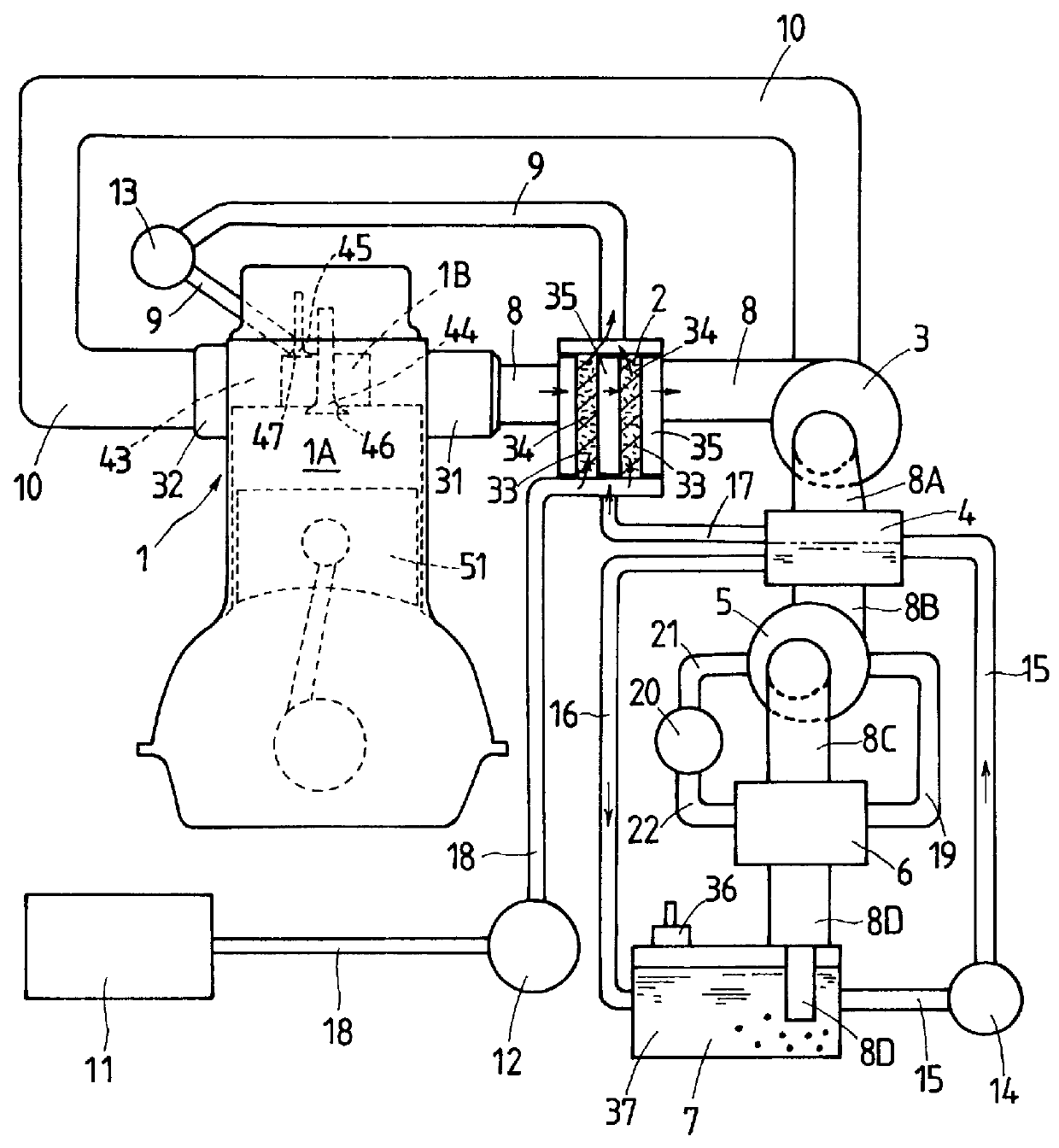
The first embodiment is a gas engine 1 using a gas fuel such as natural gas, which is a single cylinder or multicylinder precombustion chamber type gas engine applicable to a cogeneration system. The combustion chamber of the gas engine 1 comprises a main combustion chamber 1A formed in a cylinder and a precombustion chamber 1B formed in a cylinder head 43 communicating with the main combustion chamber 1A through a communication port 46. The precombustion chamber 1B to which reformed gas fuel is supplied is communicated to the main combustion chamber 1A by the opening of the communication port 46 by a control valve 44. In this gas engine, the reformed fuel is supplied to the precombustion chamber 1B from a reformed fuel supply passage 9 by a fuel valve 45 in the precombustion chamber 1B by opening a fuel supply port 47. Next, the air blown into the precombustion chamber 1B from the main combustion chamber 1A when the communication port 46 of the valve 44 opens mixes with the reforme...

second embodiment

Next, by referring to FIG. 4, let us explain about the gas engine having a gas fuel reforming device of this invention.

The second embodiment has a virtually similar construction to the first embodiment except for the CO.sub.2 extracting system. Thus, components having identical functions with those of the first embodiment are assigned like reference numerals and their explanations are not repeated.

The gas engine 1 of the second embodiment differs from the first embodiment in the CO.sub.2 supply device. The CO.sub.2 supply device comprises a CO.sub.2 separation device or separator 38 which is installed in an exhaust passage 8D to pass the low-temperature exhaust gas and which accommodates a CO.sub.2 separation membrane 40. The exhaust gas is supplied from the exhaust passage 8D to the CO.sub.2 separation device 38 that separates CO.sub.2 from the exhaust gas by the CO.sub.2 separation membrane 40. The separated CO.sub.2 is then delivered by a CO.sub.2 supply pump 42 through the CO.su...

third embodiment

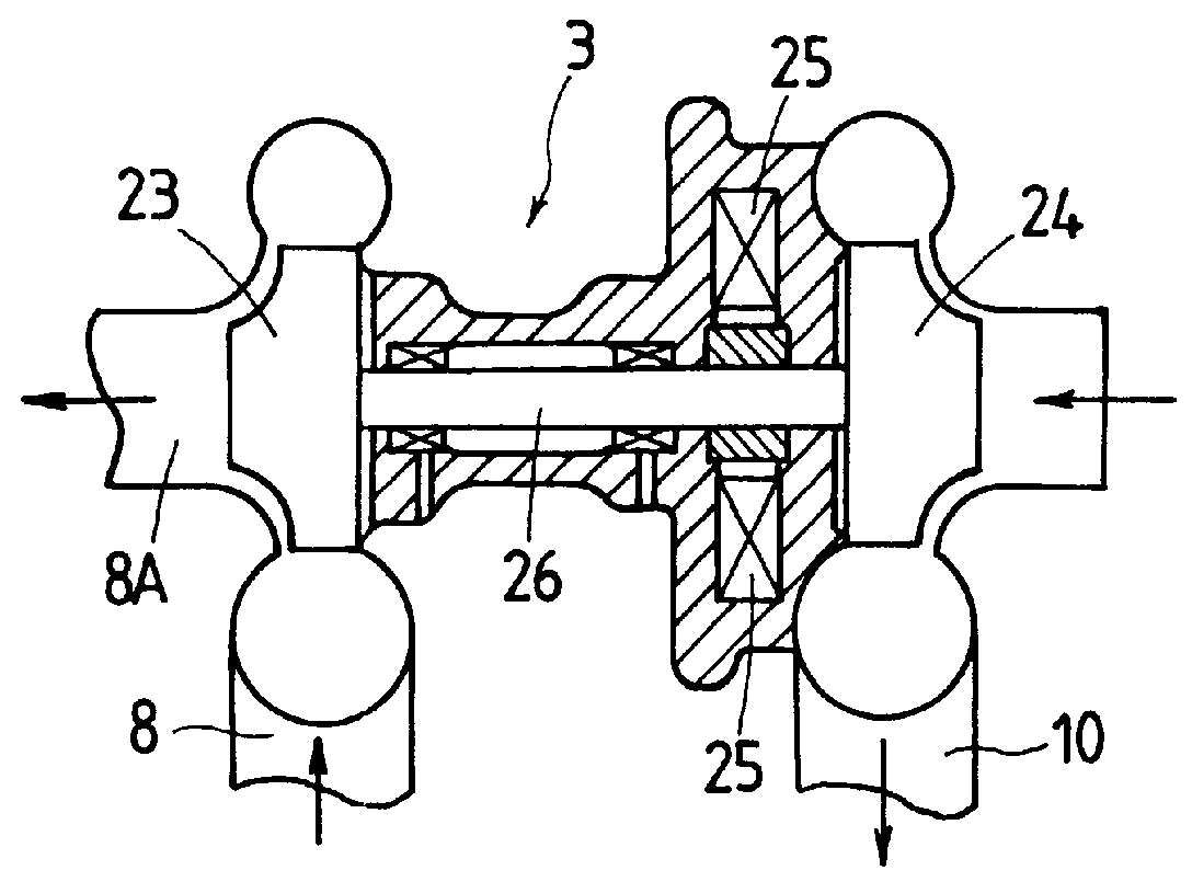
The third embodiment can use the turbocharger 3 of FIG. 2 and thus its explanations are omitted.

The first-stage heat exchanger 54 comprises steam passages 85 and exhaust gas passages 78. The steam passages 85 are installed in a first casing and contains a porous ceramic member through which the steam heated by the second-stage heat exchanger 56 flows. The exhaust gas passages 78 are arranged around the steam passages 85 and contains porous ceramic members through which the exhaust gas flows. The second-stage heat exchanger 56 comprises water-steam passages 86 and exhaust gas passages 79. The water-steam passages 86 are installed in a second casing adjacent to the first casing and contain porous ceramic members through which the steam flows and which can retain water. The exhaust gas passages 79 are arranged around the water-steam passages 86 and contains a porous ceramic member through which the exhaust gas from the first-stage heat exchanger 54 flows.

In the exhaust passage 8A downs...


PUM


Abstract

The gas engine with a gas fuel reforming device thermally decomposes CH4, a major component of natural gas, into a reformed fuel of CO and H2 to increase the heat produced and thereby reduce the CO2 content in the exhaust gas and prevent the formation of NOx. The gas engine mixes CH4 with CO2 and sends the gas mixture to the catalyst reactor installed in the exhaust passage where the gas mixture is thermally decomposed into a reformed fuel by using the thermal energy of the exhaust gas. CO2 is extracted from the exhaust gas by the CO2 supply device which in turn sends the CO2 to the catalyst reactor. The CO2 supply device comprises a CO2 dissolving device that accommodates a solution to dissolve CO2 of low-temperature exhaust gas and a CO2 delivery device installed in the exhaust passage through which high-temperature exhaust gas flows and adapted to release CO2 from the solution supplied from the CO2 dissolving device. The CO2 supply device can be formed of a CO2 separation membrane that separates CO2 from the exhaust gas.

Description

1. Field of the InventionThe present invention relates to a gas engine having a gas fuel reforming device that reforms a gas fuel such as natural gas with a thermal energy of exhaust gas to enhance the thermal efficiency.2. Description of the Prior ArtGas engines using natural gas as a main fuel are being developed as cogeneration systems. The cogeneration system extracts power in the form of electric energy by a generator and also heats water with the heat of the exhaust gas by a heat exchanger to produce hot water for use in a hot-water-supply system.Engines using natural gas as a fuel includes, for example, Japanese Patent Laid-Open No. 108865 / 1994 and 101495 / 1994.The cogeneration type gas engine disclosed in Japanese Patent Laid-Open No. 108865 / 1994 passes exhaust gas through a turbocharger, an energy recovery device and a steam generation device to reduce the exhaust gas temperature and then uses the reduced temperature exhaust gas in an exhaust gas recirculation (EGR) system t...

Claims


Application Information

Patent Timeline
Patent Type & Authority Patents(United States)
IPC IPC(8): F02B43/00F02B43/10F01N3/08F02B37/00
CPCF01N3/0857F02B43/10F02B37/00Y10S123/12Y02T10/20Y02T10/32Y02T10/12Y02T10/30
Inventor KAWAMURA, HIDEO
Owner ISUZU MOTORS LTD
Why Eureka
Try Eureka