Direct fired outdoor heater and heating method

a technology of outdoor heaters and heating methods, applied in the field of direct-fired heating appliances, can solve the problems of wasting energy in natural draft systems, not easy to replace, damage to fuel manifolds or burners, etc., and achieves the effects of reducing the operational life of components, improving combustion emissions, and convenient servi

Inactive Publication Date: 2000-10-31
ZODIAC POOL SYST
View PDF13 Cites 18 Cited by
  • Summary
  • Abstract
  • Description
  • Claims
  • Application Information

AI Technical Summary

Benefits of technology

In conventional heaters having both natural and fan-induced draft systems, high temperatures are typically experienced in and around the heater due to heat transfer from the combustion chamber through the housing. Combustion and electrical components that may be utilized to control operation of the heater are typically disposed on or near the housing. Exposure of these components to the high temperature of the heater is damaging to and reduces the operational life of the components. Furthermore, an appliance that loses excessive heat through its housing may be inefficient. Additional fuel must be expended and a larger heating appliance may be required to induce the same heat gain in the pool water when heat is lost to the atmosphere rather than transferred into the pool water. An excessively hot housing also poses a risk to people and property in the vicinity of the appliance. Therefore, a need also exists for a heater that prevents exposure of combustion and electrical components to high temperatures and recovers heat from the housing.
Thus, there is a need for a heater that may be more easily serviced, offers improved combustion emissions, has cooler external surface temperatures and has a longer service life.

Problems solved by technology

While conventional fuel manifolds can effectively distribute fuel to a burner, a shortcoming of such manifolds is that they are not easily replaced.
The barbed coupling members of a conventional fuel manifold engage the burner such that disengagement is difficult and may be damaging to the fuel manifold or burner.
Thus, when a manifold becomes damaged or a new fuel is desired to be utilized, conventional burner and manifold assemblies are typically replaced in their entirety.
The result is that natural draft systems waste energy because the flue products must be maintained at a high temperature to insure that air circulation is adequate to prevent heat damage to the heater and to prevent the buildup of hazardous products of combustion.
In outdoor applications, the use of natural drafting appliances is also problematic because wind may overcome the natural draft created by the heated flue gasses, thereby preventing proper air circulation through the appliance.
The baffles, however, restrict airflow both by the friction of the air against the many baffle sections and the redirection of the air by the baffles, thereby reducing, rather than improving, circulation through the appliance.
Appliances so constructed often experience poor combustion, soot build up and a tendency for flames to roll out of the appliance.
The pressurize combustion chamber, however, creates a potential for flames to escape from the appliance should the combustion chamber become breached.
A heater utilizing a supply fan is subject to the effects of rain because of the direct exhaust pathway and so is not well suited to outdoor use.
Venting fans are typically even more costly than combustion air fans because they must be designed to operate under high temperature conditions.
Venting fans may also create turbulence in the combustion chamber which can adversely affect combustion.
Certain previous venting fan covers, however, have prevented free passage of flue gasses out of the appliance, resulting in the collection of corrosive condensation from the flue gas on components of the appliance.
Exposure of these components to the high temperature of the heater is damaging to and reduces the operational life of the components.
Furthermore, an appliance that loses excessive heat through its housing may be inefficient.
An excessively hot housing also poses a risk to people and property in the vicinity of the appliance.

Method used


Image

  • Direct fired outdoor heater and heating method
  • Direct fired outdoor heater and heating method
  • Direct fired outdoor heater and heating method

Examples


Embodiment Construction

It is to be understood that the figures and descriptions of the present invention included herein illustrate and describe elements that are of particular relevance to the present invention, while eliminating, for purposes of clarity, other elements found in a typical direct fired heating appliance of a known construction. Because the construction and implementation of such other elements are well known in the art, and because a discussion of them would not facilitate a better understanding of the present invention, such a discussion is not provided herein. It is also to be understood that the embodiments of the present invention that are described herein are illustrative only and are not exhaustive of the manners of embodying the present invention. For example, it will be recognized by those skilled in the art that the present invention may be readily adapted to function in conjunction with a variety of appliances that require air circulation or fuel distribution.

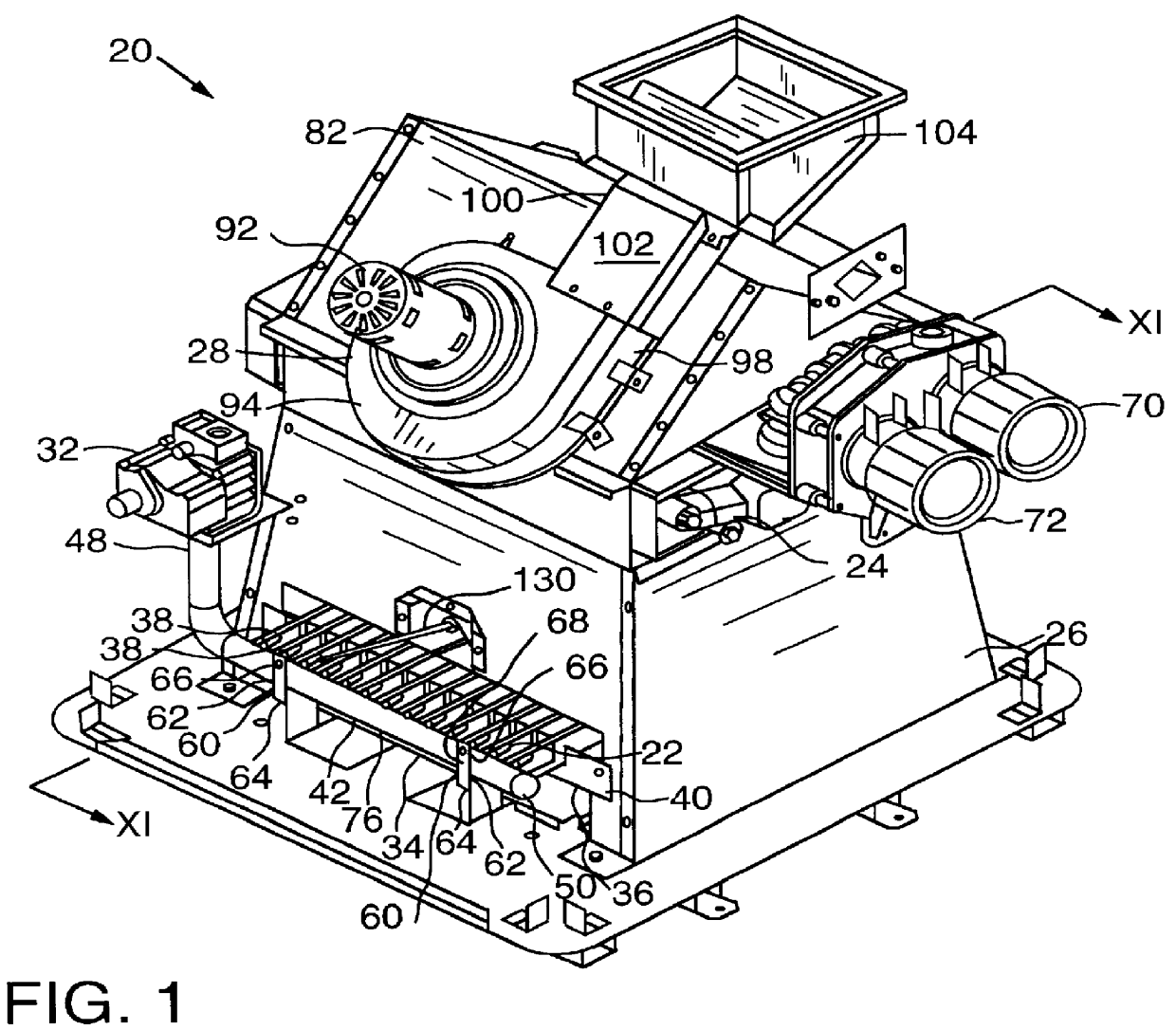
FIG. 1 is a perspec...


PUM


Abstract

A heater includes a housing having an angled top, a fan having a discharge disposed parallel to the angled top of the housing, and a baffle for laminarizing airflow through the heater. The heater may also create airflow through a cover, across a housing, a heat sensitive component, and/or a raceway, and into a housing inlet. The heater may include a manifold having at least one coupling member that slidingly engages and disengages a burner. Methods for propelling combustion air through a heater, laminarizing combustion airflow in a heater, improving the efficiency of a heater, and converting a heater to make it compatible with a different fuel are also disclosed.

Description

Not Applicable.Not Applicable.1. Field of the InventionThe present invention relates to a heating appliance and, more particularly, to a direct fired heating appliance suitable for outdoor use.2. Description of the Invention BackgroundA variety of direct fired heating appliances have been developed and are commonly used to heat fluids, such as water or glycol, or gasses, such as air. The term "direct fired" typically indicates that fuel is burned directly within the heater to create heat which is used to warm a desired medium. In one application, a direct fired heater is utilized to warm water in a swimming pool or spa. A typical heater employed to heat pool or spa water includes a burner assembly and a heat exchanger assembly enclosed in a housing.A typical burner assembly includes a burner subassembly, a fuel distribution assembly and an igniter. Fuel is supplied to the fuel distribution assembly through a fuel supply line. The fuel is regulated and distributed to the burner subas...

Claims


Application Information

Patent Timeline
Patent Type & Authority Patents(United States)
IPC IPC(8): F23L5/02F23D14/04F24H1/40F24H9/18F24H1/22F23L5/00
CPCF23D14/045F24H9/1836F24H1/40F23L5/02
Inventor HUBBARD, MICHAEL J.
Owner ZODIAC POOL SYST
Why Eureka
Try Eureka