Nanopost arrays and process for making same

a technology of nanopost arrays and nanoposts, applied in the field of nanopost arrays and process for making same, can solve the problems of high cost, complicated and expensive, and the development stage of most non-template techniques is still in progress, and achieves the effects of reducing the cost of production, and improving the quality of nanopost arrays

Inactive Publication Date: 2001-02-13
THE UNITED STATES OF AMERICA AS REPRESENTED BY THE SECRETARY OF THE NAVY
View PDF11 Cites 147 Cited by
  • Summary
  • Abstract
  • Description
  • Claims
  • Application Information

AI Technical Summary

Benefits of technology

It is an object of this invention to reliably and reproducibly deposit by electroplating a material in channels of a nanochannel glass template in an inexpensive manner.

Problems solved by technology

To date, most of the non-template techniques are still in the developmental stage, are complicated, and expensive.
Electron beam lithography, however, suffers serious disadvantages, including the high complexity and cost.
In addition, only very limited field, smaller than about 100.times.100 microns may be patterned each time, and because of thermal drift and mechanical vibration, it is virtually impossible to coherently stitch multiple fields together to fabricate very large periodic structures containing submicron features.
Nevertheless, because it uses electron beam lithography to write its masks, X-ray lithography faces the same problems that electron beam lithography suffers.
Furthermore, X-ray sources and masks can be quite expensive.
Previous alternative techniques for fabricating nanopost arrays using templates have also been limited by the lack of good templates.
The templates commonly used included polycarbonate track-etched membranes and anodized aluminum, both of which suffer several disadvantages compared to the nanochannel glass templates.
Though better than polycarbonate track-etched membrane nanoposts, anodized aluminum nanoposts are only approximately parallel and cylindrical, and non-uniform in diameter.
Nanowires fabricated by this method, however, are curly, non-uniform in diameter, randomly distributed, and mostly discontinuous.
In short, the non-uniformity of the previous templates has led to non-uniformity in the resulting ferromagnetic nanopost arrays, which consequently are not applicable for use as magnetic standards.

Method used


Image

  • Nanopost arrays and process for making same
  • Nanopost arrays and process for making same

Examples


example 2

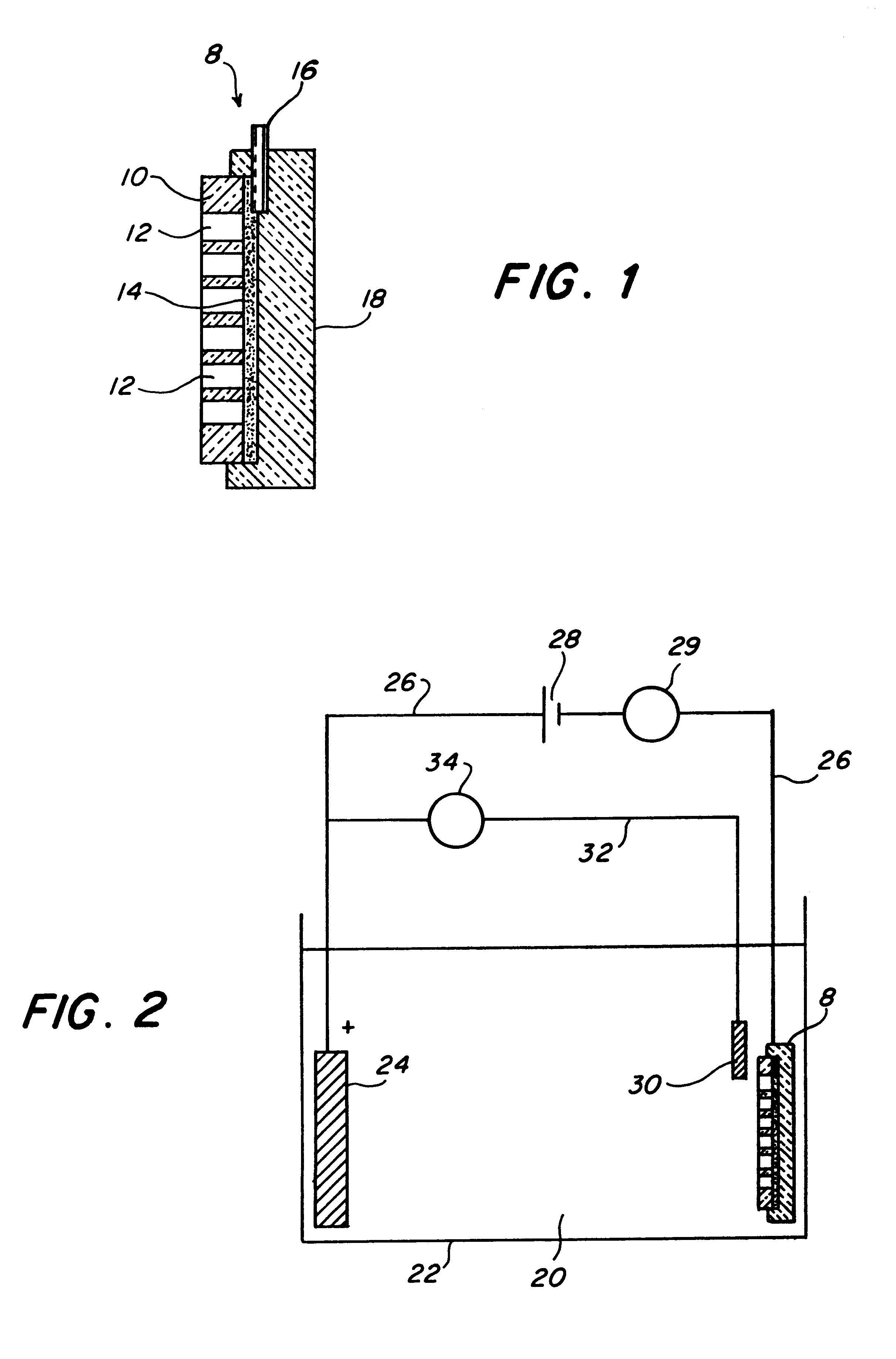
This example demonstrates preparation of a nanochannel glass array using the electroplating apparatus of FIG. 2 wherein posts in the channels were made of cobalt and had diameter of 80 nm. The nanochannel glass template was about 19 mm diameter and the hole drilled into the glass cover slip was about 0.5 mm in diameter.

After mounting the nanochannel glass template over the hole in the glass cover slip with 5-minute epoxy, a chromium film 200 nm thick was sputtered onto one side of the glass template and a wire connection was secured to the chromium film. More of the 5-minute epoxy was used to electrically isolate the sputtered side. The counter electrode was still the same as in Ex. 1, as was the reference electrode. Homemade plating solution of pH of 3.6 was 252 g / l CoSO.sub.4.7H2O, 7 g / l NaCl, and 50 g / l H.sub.3 BO.sub.3.

The electrodeposition process was carried out at around 1.8 volts in about 4 hours using the plating apparatus of FIG. 2 and in the manner described in Ex. 1, abo...


PUM

PropertyMeasurementUnit
diameteraaaaaaaaaa
diametersaaaaaaaaaa
voltageaaaaaaaaaa

Abstract

A nanopost glass array contains up to 1012/cm2 of magnetizable nanoposts having diameter of 10-1000 nm that are straight and parallel to each other and are typically of a uniform diameter relative to each other and along the post length. The array is made using a reference electrode and a nanochannel glass template structure connected to each other electrically through an electrical source and both disposed in a plating solution. A magnetizable material is electroplated from the plating solution into the channels of the template structure.

Description

1. Field of the InventionThis invention pertains to nanopost arrays containing millions of nanosize posts per square centimeter and a process for making them from nanochannel templates.2. Description of Related ArtMicromagnetic microscopy has been critical to both the physics and applications of micromagnetism. With the recent advent of new techniques, such as magnetic force microscopy and magnetic scanning near-field optical microscopy, the need for reliable and inexpensive submicron magnetic standards has grown stronger than ever before. Fabrication of large-scale nanopost arrays of ferromagnetic posts or wires and their application as magnetic standards and others is presented herein. Nanopost glass arrays made from the glass templates each containing more than several million nanometer-scale cylindrical channels that are parallel and uniform in diameter. The geometric placement of the channels in the template can be controlled to a high degree. The nanopost glass arrays can be u...

Claims


Application Information

Patent Timeline
Patent Type & Authority Patents(United States)
IPC IPC(8): C03C17/10C03C17/06H01F41/00H01F1/00H01F41/30H01F41/34H01F41/14
CPCB82Y25/00B82Y40/00C03C17/10H01F1/009H01F41/30H01F41/34C03C2217/261C03C2218/11C03C2218/32
Inventor TONUCCI, RONALD J.NGUYEN, PAUL P.
Owner THE UNITED STATES OF AMERICA AS REPRESENTED BY THE SECRETARY OF THE NAVY
Why Eureka
Try Eureka