Solar battery module for optical electrolysis device and optical electrolysis device

a technology of optical electrolysis and solar cells, which is applied in the direction of electrolysis components, pv power plants, energy input, etc., can solve the problems of low energy conversion efficiency with respect to sunlight, inability to use technology in practical use, and difficulty in increasing the light utilization rate in making use of light in a light spa

Inactive Publication Date: 2001-03-06
SPHELAR POWER
View PDF8 Cites 56 Cited by
  • Summary
  • Abstract
  • Description
  • Claims
  • Application Information

AI Technical Summary

Benefits of technology

Another purpose of this invention is to provide a solar battery module for a photoelectrolytic device that can prevent overvoltage at the electrolysis electrodes and can promote the separation of reaction products from the electrodes. Another purpose of this invention is to provide a solar battery module for a photoelectrolytic device that has electrolysis electrodes having a catalytic function. Another purpose of this invention is to provide a photoelectrolytic device in which the solar battery module for a photoelectrolytic device is applied.
Here, it is desirable to set the number of the multiple spherical solar battery elements in accordance with the voltage of the photoelectromotive force to be generated by the photoelectromotive force generation part and the electrolysis voltage needed for the electrolyte. On each surface of the pair of electrolysis electrodes it is desirable to form a metal form that has a catalytic function that promotes electrolytic reactions. And it is desirable to form on the part of the electrolysis electrodes that comes into contact with the electrolyte a pointy tip in order to reduce the overvoltage and promote the separation of reaction products.
In the solar battery module for a photoelectrolytic device, multiple spherical solar battery elements are accommodated in a transparent holding member in a state in which they are connected electrically in series, so a photoelectromotive force is generated by light that is incident from various directions. The size of the photoelectromotive force can be set freely by varying the number of series-connected spherical solar battery elements, which provides superior generality that can be applied to various photoelectrolytic devices. By forming a metal film that has a catalytic function on the surface of the electrolysis electrodes, the electrolysis can be speeded up by the catalytic effect. And by forming a pointy tip on the electrolysis electrodes, overvoltage can be reduced and the separation of reaction products can be promoted.
The photoelectrolytic device of this invention is characterized in that it has a container that accommodates an electrolyte inside it and into which sunlight can be introduced; multiple solar battery modules that are arranged in a state in which they are immersed in an electrolyte inside this container, receive sunlight, and generate photoelectromotive force; and a partition member that partitions the space between the electrolysis anode and the electrolysis cathode of these solar battery modules to make it possible to separate the reaction products produced at both electrodes, and on which multiple solar battery modules are piercingly mounted.
When sunlight shines onto this photoelectrolytic device, a photoelectromotive force is generated in the multiple solar battery modules, oxidation reactions occur at the electrolysis anode of each solar battery module, and reduction reactions occur at the electrolysis cathode. Because a partition member is provided that forms a partition between the anode and cathode to make it possible to separate the reaction products that are produced at both electrodes, the oxidation reaction products and the reduction reaction products can be removed to the outside while remaining separated by the partition member. Moreover, multiple solar battery modules are mounted piercingly on this partition member, simplifying the composition for mounting and supporting multiple solar battery modules.

Problems solved by technology

Heretofore there have been attempts in which water is electrolyzed by the photoelectromotive force produced by titanium oxide (TiO.sub.2), but because the wavelength of the light that allows energy conversion with titanium oxide is about 420 nm or less, the energy conversion efficiency with respect to sunlight is very low, and this technology has not been put to practical use.
But with the technology described in these two documents, the direction in which sunlight can be received is limited to one surface, making it difficult to increase the light utilization rate in making use of the light in a light space.
This makes it difficult to reduce the cost of fabricating solar battery arrays and arrays of light receiving elements suitable for photoelectrolytic devices, and makes it difficult to fabricate solar battery arrays and arrays of light receiving elements of wide application suitable for photoelectrolytic devices of various types and sizes.
In a photoelectrolytic device of this kind, it is necessary to support many small-particle spherical semiconductor devices in an electrolyte arranged so they can receive light, and to surely separate the reaction products, but as yet no structure has been proposed for thus arranging and supporting a large number of spherical semiconductor devices.

Method used


Image

  • Solar battery module for optical electrolysis device and optical electrolysis device
  • Solar battery module for optical electrolysis device and optical electrolysis device
  • Solar battery module for optical electrolysis device and optical electrolysis device

Examples


example 1 (see figs.1-3)

Example 1 (see FIGS. 1-3)

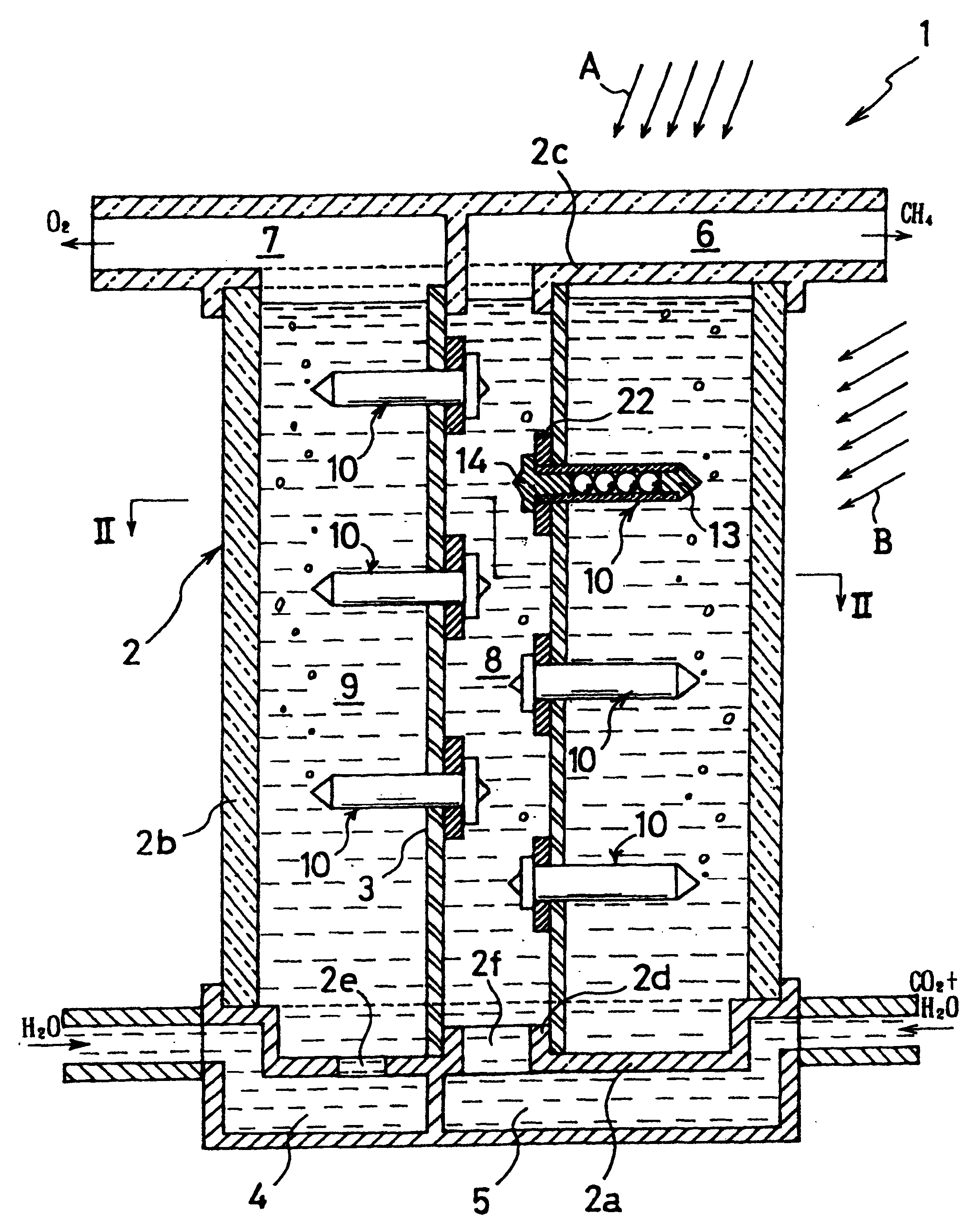
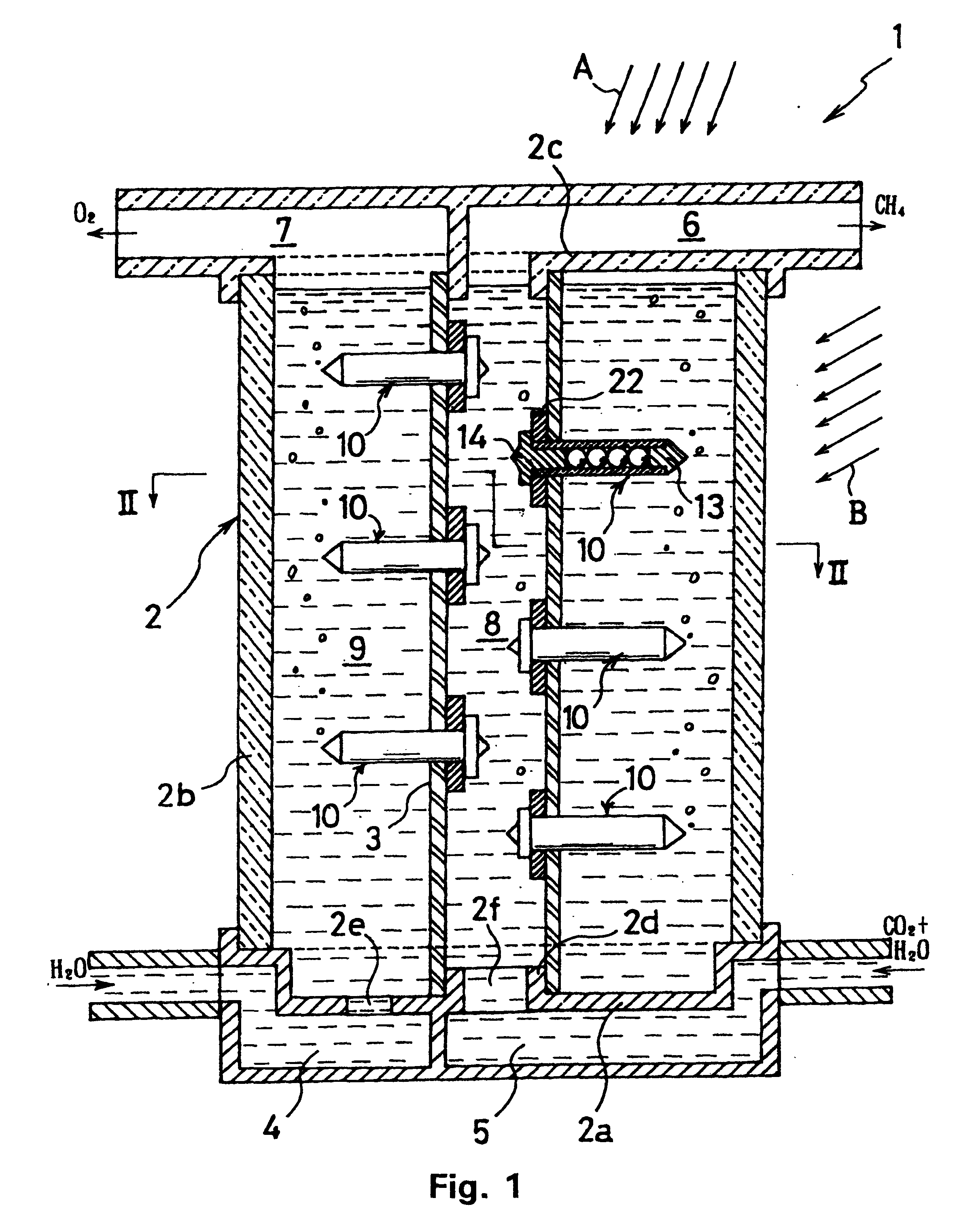
Photoelectrolytic device 1 in this example is a device that electrolyzes, by the photoelectromotive force produced by solar energy, an electrolytic solution of water and carbon dioxide gas, producing methane gas (CH.sub.4) and oxygen gas (O.sub.2).

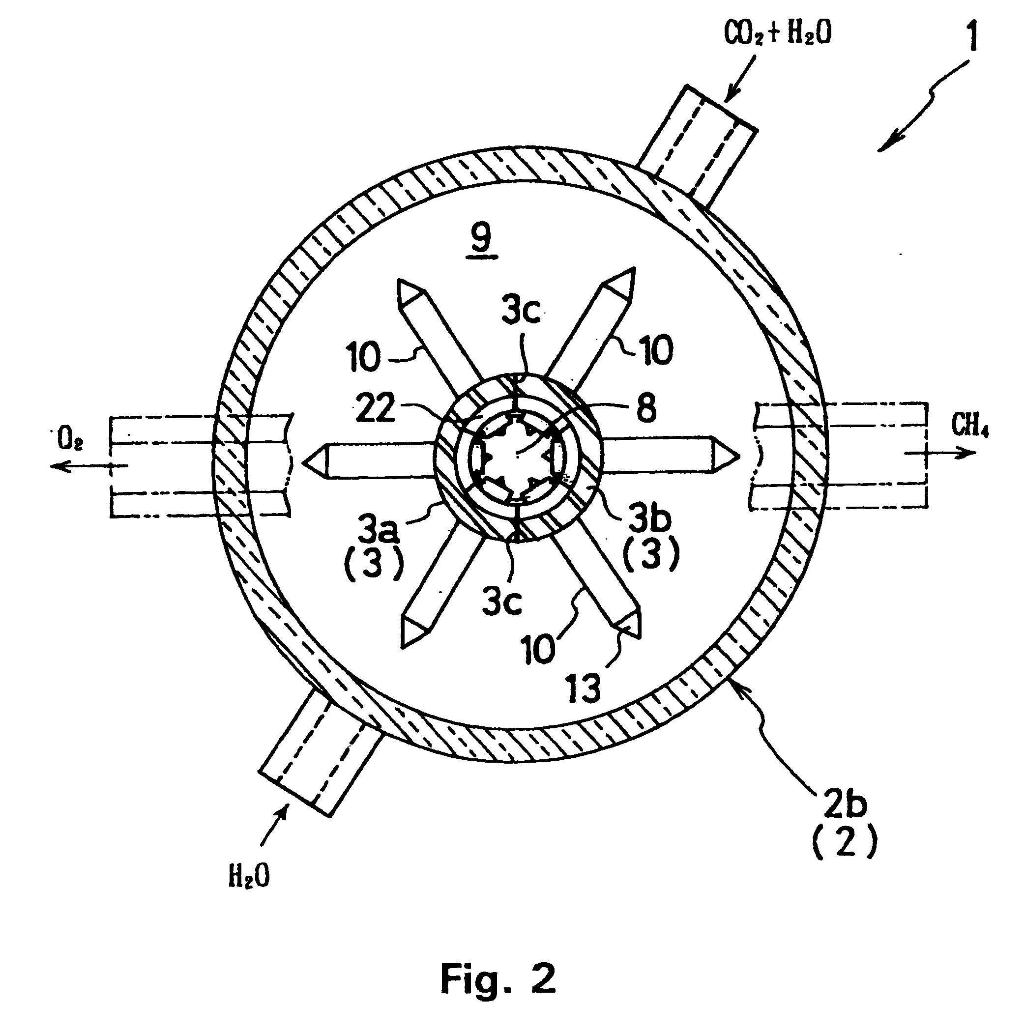
As shown in FIGS. 1 and 2, this photoelectrolytic device 1 has a container 2 of circular cross-section that accommodates the electrolyte, a cylindrical partition member 3 provided in the center of this container 2, multiple solar battery modules 10 mounted on this partition member 3 and piercing it radially, first supply port 4 for supplying water and second supply port 5 for supplying carbon dioxide gas formed on the base wall part 2a of container 2, and first lead-out port 6 for taking out the methane gas and second lead-out port 7 for taking out the oxygen gas, each formed in pipe shape integrally with cover part 2c of container 2.

The container 2 has base wall part 2a, which is made of stainless steel or another...

example 2 (see figs.5-7)

Example 2 (see FIGS. 5-7)

Photoelectrolytic device 30 in this example is a device that produces hydrogen gas (H.sub.2) and oxygen gas (O.sub.2) by electrolyzing water as the electrolyte, powered by the photoelectromotive force generated by solar energy.

As shown in FIGS. 5 and 6, this photoelectrolytic device 30 has container 31, which has a circular cross-section, partition member 34, which partitions its interior into reduction reaction chamber 32 and oxidation reaction chamber 33, and, for example, 15 solar battery modules 35, which are mounted piercingly on this partition member 34. This container 31 has base wall 31a, cylindrical wall part 31b, which is integral with this base wall 31a, and cover plate 31c, which covers the upper end of this cylindrical wall part 31b so that it can be opened and closed. Fixed in mutually facing positions on the inside surface of cylindrical wall part 31b are guide members 36, which are made of quartz glass or stainless steel and in which are form...

example 3 (see fig.8)

Example 3 (see FIG. 8)

As in the above example 2, photoelectrolytic device 50 in this example is a device that produces hydrogen gas (H.sub.2) and oxygen gas (O.sub.2) by electrolyzing water as the electrolyte, powered by the photoelectromotive force generated by solar energy.

As shown in FIG. 8, this photoelectrolytic device 50 has box-shaped container 51, which is made of, for example, sheet stainless steel; cover plate 52, which is made of transparent glass and covers the upper end of container 51 so that it can be opened and closed; five partition plates 54 (partition members) that partition the interior of container 51 into six reaction chambers 53a and 53b; for example, 21 solar battery modules 55 mounted in each partition plate 54; water supply tube 59; oxygen gas lead-out tube 57; and hydrogen gas lead-out tube 58. On the inside surface of the side walls at the front and back of container 51 are glass or stainless-steel guide members 56 for mounting partition plates 54, and fi...


PUM

PropertyMeasurementUnit
thicknessaaaaaaaaaa
electrolysis voltageaaaaaaaaaa
overvoltageaaaaaaaaaa

Abstract

Partition member 34 is provided, which partitions the interior of glass container 31 into reduction reaction chamber 32 and oxidation reaction chamber 33 and which is made of a polymer electrolyte that conducts hydrogen ions; solar battery modules 35 are mounted on this partition member 34, for example in a matrix arrangement of five rows and three columns; a solar battery module 35 has a photocell array (photoelectromotive force: 2.0-2.4 V) consisting of four spherical solar battery elements (photoelectromotive force: 0.5-0.6 V) connected in series, anode 46, and cathode 48; solar battery modules 35 are mounted on partition member 34 so that anode 46 is in contact with the electrolyte of oxidation reaction chamber 33 and cathode 48 is in contact with the electrolyte of reduction reaction chamber 32; sunlight is shined on solar battery modules 35, and the photoelectromotive force electrolyzes the water and produces hydrogen gas from cathode 48 and oxygen gas from anode 46.

Description

This invention concerns a solar battery module for a photoelectrolytic device and a photoelectrolytic device that employs the solar battery module; in particular, it concerns technology in which the electrolysis of an electrolyte is carried out by solar energy using a solar battery module in which multiple spherical solar battery elements are connected in series and that generates the required electrolysis voltage.BACKGROUND TECHNOLOGYHeretofore there have been attempts in which water is electrolyzed by the photoelectromotive force produced by titanium oxide (TiO.sub.2), but because the wavelength of the light that allows energy conversion with titanium oxide is about 420 nm or less, the energy conversion efficiency with respect to sunlight is very low, and this technology has not been put to practical use. Heretofore, technology to electrolyze an electrolyte with the photoelectromotive force of sunlight by means of a solar battery immersed in the electrolyte has appeared in U.S. Pa...

Claims


Application Information

Patent Timeline
Patent Type & Authority Patents(United States)
IPC IPC(8): C25B1/00H01L31/0352H01L31/0248H01L31/048C25B9/00H01L31/04
CPCC25B1/003H01L31/035281H01L31/048Y02E10/50Y02E60/368Y10S205/923C25B1/55H01L31/02008H01L31/0504Y02E60/36Y02P20/133H01L31/042H01L31/06
Inventor NAKATA, JOSUKE
Owner SPHELAR POWER
Why Eureka
Try Eureka