Target assembly for ion beam sputter deposition with multiple paddles each having targets on both sides

a target assembly and ion beam technology, applied in the direction of electrolysis components, vacuum evaporation coatings, coatings, etc., can solve the problems of low film deposition rate, increased possibility of contamination of deposited films, poor thickness uniformity of deposited films,

Inactive Publication Date: 2001-05-01
VEECO INSTR
View PDF18 Cites 67 Cited by
  • Summary
  • Abstract
  • Description
  • Claims
  • Application Information

AI Technical Summary

Benefits of technology

An object of the present invention is to overcome the above-noted disadvantages of ion beam sputter deposition compared with other modes of ion sputter deposition, thus enabling the benefits and controllability of ion beam sputter deposition to be utilized in a wide variety of thin film deposition applications.

Problems solved by technology

The three chief disadvantages of ion beam sputter deposition are low film deposition rate, poor thickness uniformity of the deposited film and increased possibilities for contamination of the deposited film, compared with other ion sputter deposition modes.
Therefore, the machine cannot simply be opened for the exchange of the sputtering target.
However, when very large targets are contemplated, that can result in a bulky, cumbersome target array.
Ion beam sputter deposition of thin films from ion beam sputter targets is limited in the chemical purity of the deposited film by the possibility of the ion beam sputtering atoms into the growing film from sources other than the intended sputter target.
Another source of chemical impurity for multi-target arrays is cross-contamination of the inactive targets by sputtered material from the active target.
On a typical, fine-grained (0.1 to 2.0 mm) polycrystalline sputter target, sputtering at those fixed angles results in a slow (hours) evolution of increasingly severe surface roughening.
However, it will be apparent that none of them overcomes the above-noted deficiencies of conventional ion sputtering.
However, that feature is not described in the specification, and even if it were taken to be a shield, such a shield would not be effective to protect inactive targets from sputtered flux from the selected target 91 (FIGS. 2 and 9; col.

Method used


Image

  • Target assembly for ion beam sputter deposition with multiple paddles each having targets on both sides
  • Target assembly for ion beam sputter deposition with multiple paddles each having targets on both sides
  • Target assembly for ion beam sputter deposition with multiple paddles each having targets on both sides

Examples


first preferred embodiment

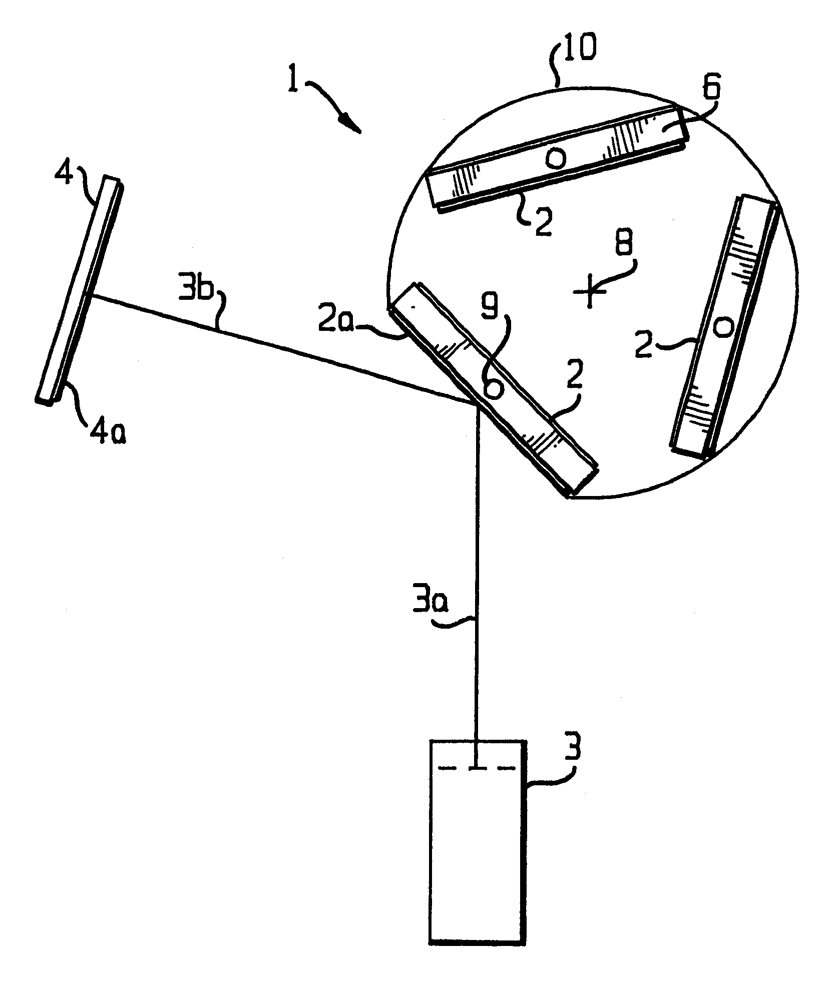
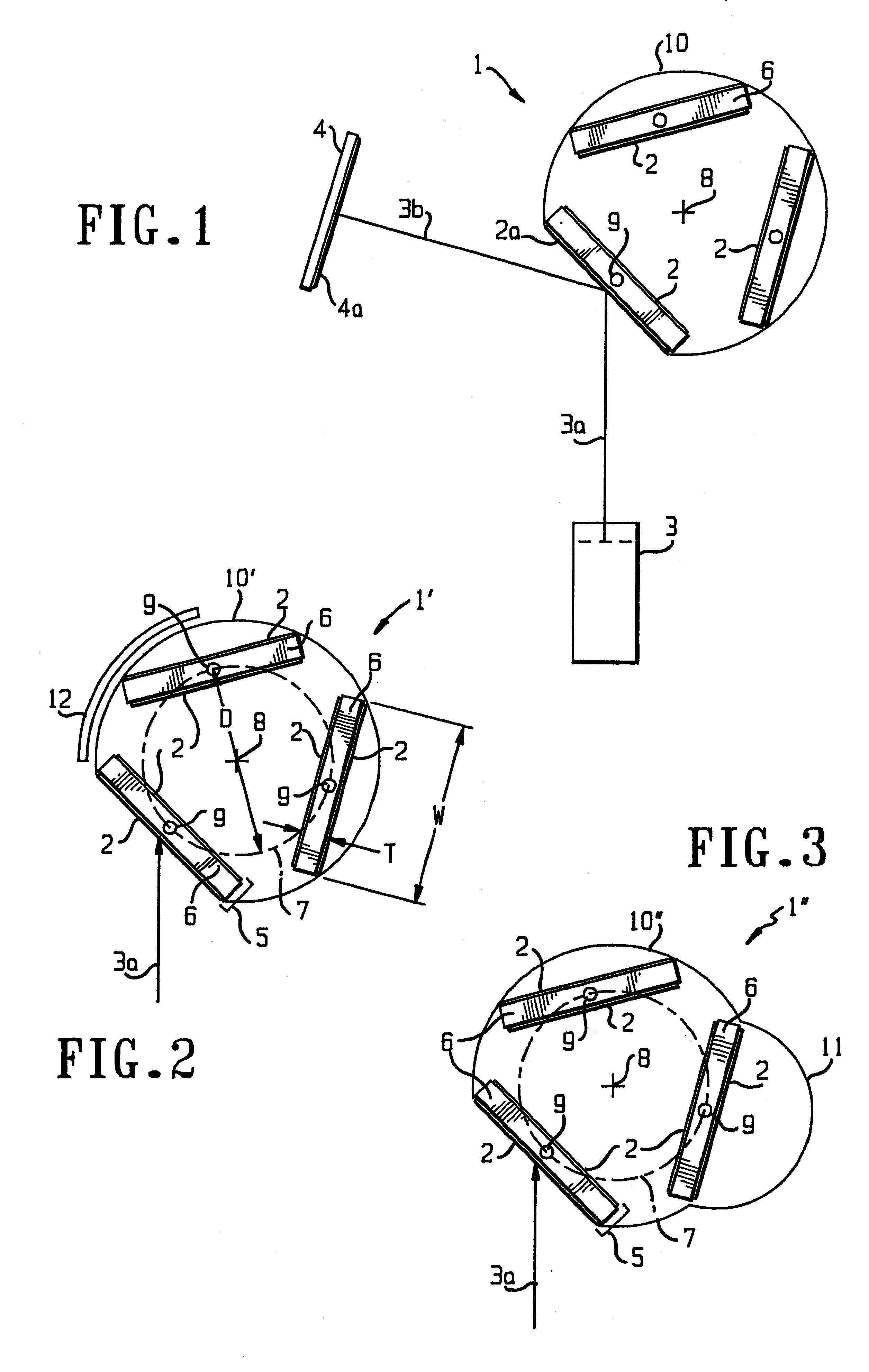
The first preferred embodiment of the ion beam sputtering target assembly 1' having six sputter targets 2 is shown in FIG. 2. The sputter targets 2 are arrayed in pairs 5, and each pair of targets is mounted back-to-back upon a substantially planar target mounting plate or paddle 6. Each of the three paddles 6, with its two targets 2, is disposed upon the circumference of a circular holder or bracket 7, equally spaced. Together, the two planar sputter targets, back-to-back, and the mounting plate form an essentially flat, planar structure a few centimeters in thickness.

The circular holder or bracket 7 supporting those target pairs 5 can be rotated about its axis 8 in such a way as to bring any one of the target pairs 5 to be exposed to the sputtering ion beam 3a so as to deposit a film 4a on a substrate 4 (not shown in FIG. 2). The identity of the target exposed to the sputtering ion beam, within each pair 5 of targets, is selected by a rotation about the axis 9 of the paddle 6 hold...

second preferred embodiment

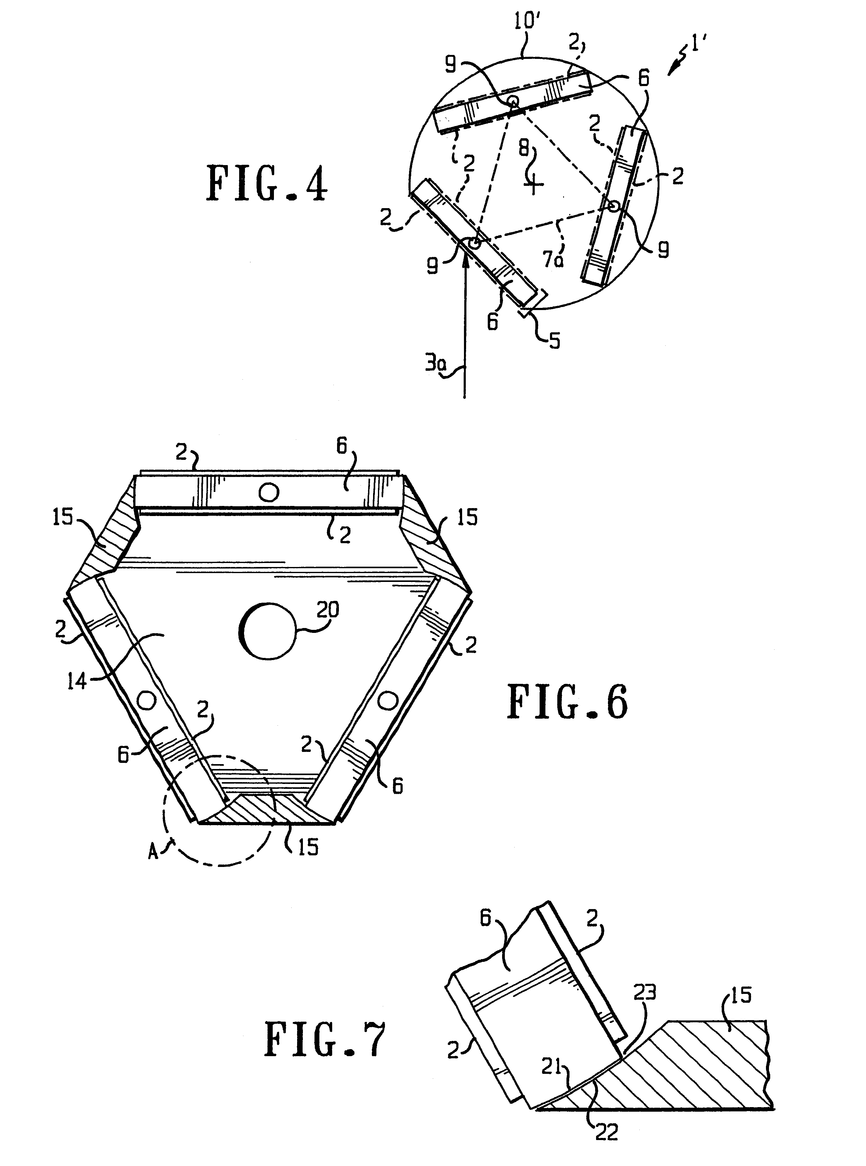
FIG. 3 shows an assembly 1" according to a second preferred embodiment of the present invention. The second preferred embodiment will be described primarily in terms of its differences from the first preferred embodiment. Features disclosed above for the first preferred embodiment, including any modifications and particularly including the modification shown in FIG. 4, can be incorporated into the second preferred embodiment.

The protective shield 10" enclosing the target assembly 1" is enlarged at a region 11 to allow one of the target paddles 6 to be rotated about its axis 9 while at one of the inactive, non-sputtering rotary positions. Therefore, whichever of the two targets 2 on a paddle 6 is rotated to face outward (away from axis 8) while the paddle is in region 11 will face the sputtering ion beam when its paddle is moved to the active position and will thus serve as the desired target 2a. The second preferred embodiment can be desirable if, for example, a physical obstruction...

working examples

The following examples are provided to illustrate the manner in which the present invention is used. These examples are illustrative and not limiting.


PUM

PropertyMeasurementUnit
thicknessaaaaaaaaaa
diameteraaaaaaaaaa
thicknessaaaaaaaaaa

Abstract

An ion beam sputtering target assembly has six sputter targets arranged in pairs on three paddles and disposed upon the circumference of a circular holder. The circular holder can be rotated about its axis in such a way as to bring any one of the target pairs to be exposed to the sputtering ion beam to deposit a film on substrate. The paddle is rotated to bring a desired target in the pair into position for sputtering. An alternative embodiment is provided with an enlarged region which allows one of the target paddles to be rotated about its axis while that target paddle is in an inactive, non-sputtering rotary position.

Description

BACKGROUND OF THE INVENTIONThe present invention is directed to an apparatus for the deposition of thin films in a substantially vacuum environment. More particularly, the present invention is directed to an apparatus for ion sputtering of a material from a sputtering target, in which individual ions having kinetic energies of several tens of electron-volts (eV) to several tens of thousands of eV strike the target surface and knock off (sputter) target atoms, and in which the target atoms thus liberated from the target surface are collected (condensed) from the vapor phase onto a substrate in the form of a thin film. Still more particularly, the present invention is directed to an ion sputter deposition apparatus in which the sputtering ions originate from an ion beam source situated some distance away from the sputter target.That mode of ion sputter deposition is well known in the art as ion beam sputter deposition and has several advantages over other ion sputter deposition modes,...

Claims


Application Information

Patent Timeline
Patent Type & Authority Patents(United States)
IPC IPC(8): C23C14/46C23C14/34H01J37/32H01J37/34
CPCC23C14/3407C23C14/46H01J37/3435
Inventor MEYER, WILLIAM A.
Owner VEECO INSTR
Why Eureka
Try Eureka