
Method and apparatus for optical flame control of combustion burners

a technology of optical flame control and burner, which is applied in the direction of combustion regulation, fuel supply regulation, burners, etc., can solve the problems of excessive fuel consumption, nox and co are very dangerous pollutants, and insufficient combustion of fuel,

Inactive Publication Date: 2001-06-12
AIR LIQUIDE AMERICA INC
View PDF25 Cites 76 Cited by
  • Summary
  • Abstract
  • Description
  • Claims
  • Application Information

AI Technical Summary

Problems solved by technology

On the other hand, incomplete combustion of a fuel generates carbon monoxide (CO).
Both NOx and CO are very dangerous pollutants, and the emission of both gases is regulated by environmental authorities.
Combustion of a fuel with an uncontrolled excess amount of air can also lead to excessive fuel consumption and increase the production cost of the final product.
However, this type of combustion control device does not give any information on the combustion mixture.
UV flame detectors are typically self contained devices that are not always integrated in the burner design.
They are generally complicated and expensive pieces of equipment that require careful maintenance.
When compressed air is used, uncontrolled amounts of air are introduced in the furnace and may contribute to the formation of NOx.
Water jackets are subject to corrosion when the furnace atmosphere contains condensable vapors.
This situation often leads the furnace operator to use a large excess of air to avoid the formation of CO.
This feed-forward combustion control strategy does not account for the air intakes that naturally occur in industrial furnaces and bring unaccounted quantities of oxidant into the firebox, nor does this control scheme account for the variation of the air intakes caused by furnace pressure changes.
Another drawback is that the response time of the feed-forward regulation loop is generally slow, and can not account for cyclic variations of oxidant supply pressure and composition that occur when the oxidant is impure oxygen, for example as produced by a vacuum swing adsorption unit or membrane separator.
Yet another drawback of the feed-forward control of combustion ratio is that the PLC should be reprogrammed at every occurrence of a change in natural gas supply and composition.
However, zirconia sensors for oxygen that are commercially available have limited lifetime and need to be replaced frequently.
One difficulty met when using these sensors is a tendency to plug, especially when the exhaust gases contain volatile species, such as in a glass production furnace.
When the furnace possesses more than one burner, a drawback of global combustion control is that it is not possible to know whether each individual burner is properly adjusted or not.
Although very efficient, these techniques are not always economically justified.
However, implementing flame light emission monitoring on industrial burners used on large furnaces is quite difficult in practice, resulting in a number of problems.
Second, the plant environment is difficult because of excessive heat being produced by the furnace.
Finally, these environments tend to be very dusty which is not favorable for the use of optical equipment except with special precautions, such as gas purging over the optical components.

Method used


Image

  • Method and apparatus for optical flame control of combustion burners
  • Method and apparatus for optical flame control of combustion burners
  • Method and apparatus for optical flame control of combustion burners

Examples


example 1

Flame Stoichiometry Monitoring.

A specific region or regions of the spectrum may be monitored to provide information on the flame stoichiometry. For example, in the combustion of natural gas (NG) and oxygen, a strong continuum in the wavelength range of 350-700 nm is present with a maximum occurring near 650 nm. Part of this continuum is thought to result from chemiluminescence from the recombination reaction of CO+O=>CO.sub.2. The strength (intensity) of this continuum has been observed to be related to whether the burner is operating near stoichiometric conditions. When operating under fuel-rich conditions the observed continuum intensity is weaker as compared to slightly fuel-lean or stoichiometric operating conditions.

The effect of stoichiometry on the flame emission spectrum is shown in FIGS. 9 and 10. These spectra were obtained using a fiber optic and lens positioned externally to the burner. Flame emission was collected through the natural gas (NG) injector and window mounted...

example 1.1

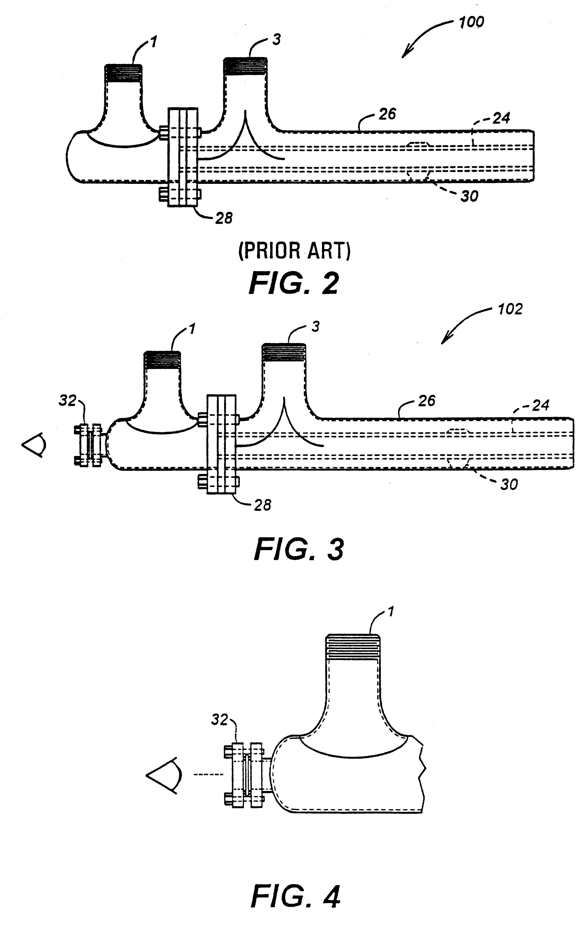
Experiments were conducted using a burner and optical coupling as illustrated in FIG. 3. The optical coupling device was attached to a standard burner known under the trade designation ALGLASS available from Air Liquide America Corp., Houston, Tex. The burner had an output of 1.2 MMBtu / hr (using oxygen 99% pure as oxidant) allowing flame emission spectra to be collected through the natural gas (NG) injector. Ultraviolet and visible flame radiation covering a spectral rage of 300-700 nm were collected for different combustion stoichiometries defined in terms of equivalence ratio (.PHI.), wherein: ##EQU1##

For stoichiometric operating conditions, .PHI.=1, whereas for fuel-lean conditions .PHI.1. Results showing the variation of the flame emission spectra for different values of .PHI. are graphically illustrated in FIG. 11. The spectra were obtained using a fiber optic and lens positioned externally to the bumer. Flame emission was collected through the natural gas (NG) injector and win...

example 1.2

The intensity of the emitted flame radiation detected depends on the wavelength region that is being observed. This wavelength dependence results from chemiluminescence of excited state chemical species, continuum emission from atom molecule reactions, and continuum emission from the presence of particles either being entrained or formed in the flame. These effects can be classified as purely chemical, i.e., the observed flame radiation is only a result of the chemical process taking place with no external influences. In addition to the pure chemical effects, other factors can influence the spectrum intensity such as characteristics of how the fuel and oxidizer are mixed, burner, background contributions, entraimnent of chemical species into the flame, furnace, and the method used to collect the radiation, e.g. optical system. Therefore the flame radiation intensity observed in a process can be expressed as a multivariable function:

I.sub..lambda. =.intg..intg..intg..function.(B, S, ...


PUM


Abstract

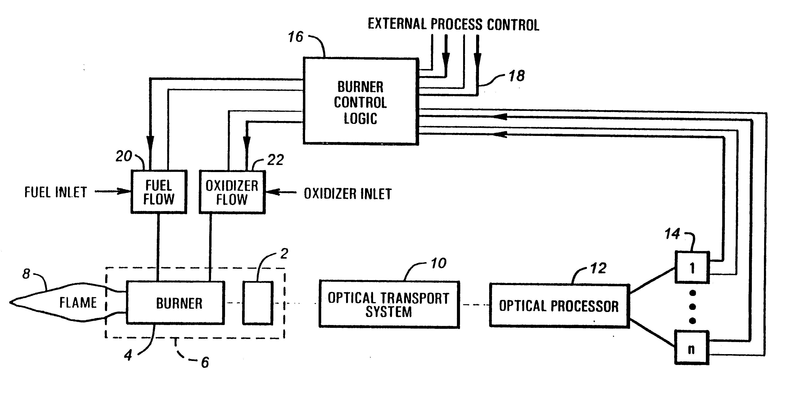
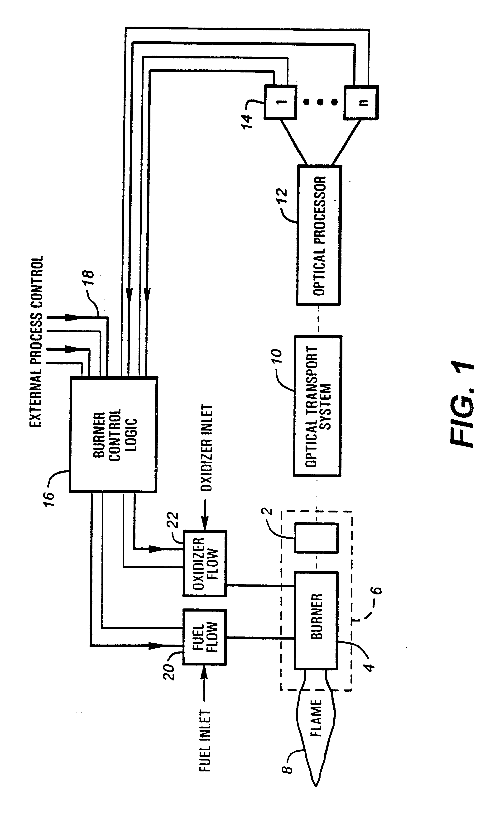
In accordance with the present invention, methods and apparatus to control the combustion of a burner are presented which overcome many of the problems of the prior art. One aspect of the invention comprises a burner control apparatus including a device for viewing light emitted by a flame from a burner, a device for optically transporting the viewed light into an optical processor, an optical processor for processing the optical spectrum into electrical signals, a signal processing for processing the electrical signals obtained from the optical spectrum, and a control device which accepts the electrical signals and produces an output acceptable to one or more oxidant or fuel flow control devices. The control device, which may be referred to as a "burner computer," functions to control the oxidant flow and / or the fuel flow to the burner. In a particularly preferred apparatus embodiment of the invention, a burner and the burner control apparatus are integrated into a single unit, which may be referred to as a "smart" burner.

Description

1. Field of the InventionThe present invention relates generally to burner control, and more specifically to methods and apparatus for controlling combustion efficiency in burners.2. Description of the Related ArtNumerous industrial processes such as glass or fritt melting, ferrous and nonferrous materials smelting, ladle preheating, billets reheating, waste incineration and vitrification, crude oil refining, petrochemical production, power plants, and the like use burners as the primary source of energy, or as an auxiliary source of energy. These burners possess one or more inlets for fossil fuels of high calorific value such as natural gas, liquefied petroleum gas, liquid hydrocarboneous fuel, and the like, which are combusted to produce heat. Some burners also comprise inlets for low calorific content gases or liquids that need to be incinerated. The fuels are burned in a combustion chamber where the energy that is released by the combustion is transferred to the furnace load. Th...

Claims


Application Information

Patent Timeline
Patent Type & Authority Patents(United States)
IPC IPC(8): F23N5/08F23N1/02
CPCF23N5/082F23N1/02F23N2035/06F23N2035/12F23N2235/06F23N2235/12
Inventor VONDRASEK, WILLIAMPHILIPPE, LOUIS C.DUCHATEAU, ERIC L.
Owner AIR LIQUIDE AMERICA INC
Learn More