
Metal matrix composite casting and manufacturing method thereof

a technology of metal matrix and composite casting, applied in the direction of metal-working apparatus, solid-state devices, metallic material coating processes, etc., can solve the problems of high cost, difficult process of making al-sic composite, and inability to reach the metal-matrix composi

Inactive Publication Date: 2001-06-12
DENSO CORP +1
View PDF27 Cites 71 Cited by
  • Summary
  • Abstract
  • Description
  • Claims
  • Application Information

AI Technical Summary

Benefits of technology

Alternatively, the processed member may be left in the metal matrix composite, and the processed portion may be formed in the processed member by a processing method such as cutting and drilling. In this case, the processed portion can be easily formed into a desired shape.
The processed member is formed from an easily processable material. However, the melting point of the processed member must be higher than that of the molten metal at the time of die-casting to maintain the shape thereof even during die-casting. The processed member having such characteristics is preferably formed from water-soluble salt, metal, a preform of metal powder, metal foaming body, metallic fiber textile, metallic fiber non-woven cloth, carbon or boron nitride fiber textile, carbon or boron nitride non-woven cloth, or a preform of carbon or boron nitride powder. As a result, the process of the processed member can be made easily.

Problems solved by technology

However, since the Al-SiC composite is very hard, it is difficult to carry out the secondary process with respect to the Al-SiC composite, and therefore, the cost thereof becomes high.
In this method, however, since the formed Al layer is thin, the process of making the Al-SiC composite is difficult due to the influence of the underlying Al-SiC composite.
Further, even if cracks occur in the processed member during formation of the screw thread, they do not reach the metal matrix composite.
If the cracks are formed in the metal matrix composite, the metal matrix composite may break with the cracks becoming the starting points.

Method used


Image

  • Metal matrix composite casting and manufacturing method thereof
  • Metal matrix composite casting and manufacturing method thereof
  • Metal matrix composite casting and manufacturing method thereof

Examples


first embodiment

(First Embodiment)

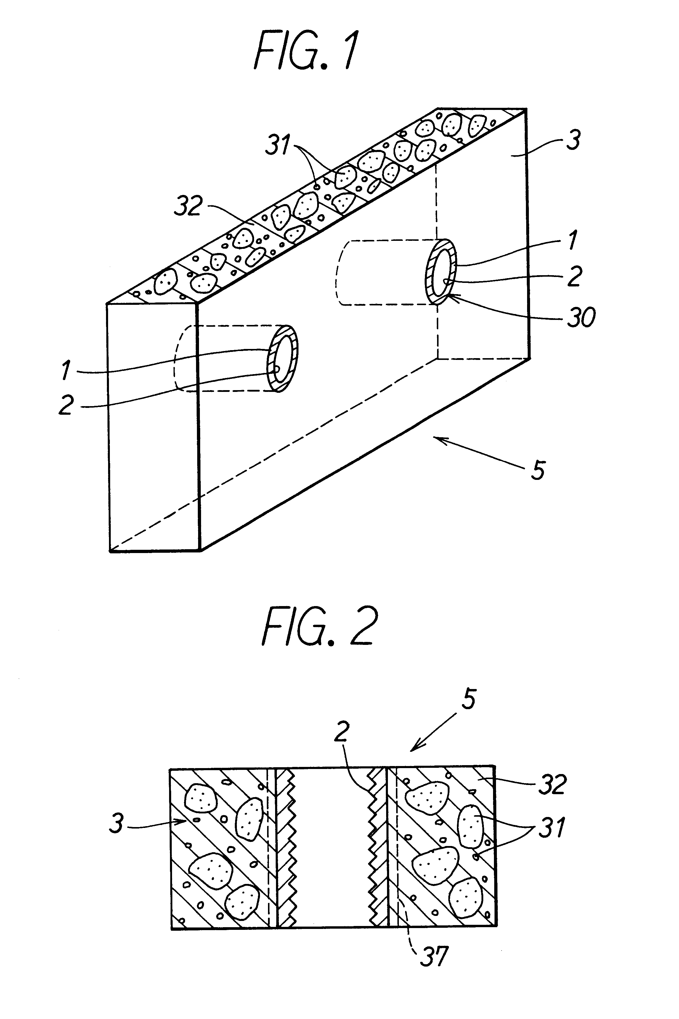
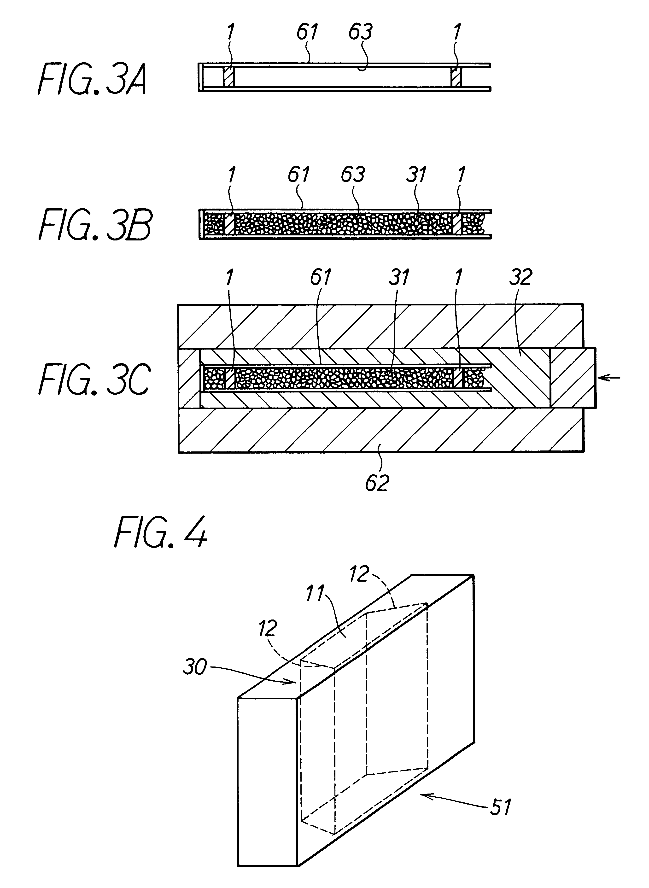
A metal matrix composite casting according to a first embodiment will be described with reference to FIG. 1 to FIGS. 3A-3C.

The metal matrix composite casting 5 is, as shown in FIG. 1, constructed from a metal matrix composite 3, and a processed member 1 inserted at a processed position 30 in the metal matrix composition 3. A processed portion 2 of a predetermined shape is formed in the processed member 1 provided at the processed position 30.

The metal matrix composite 3 is formed from aluminum alloy (hereinafter, referred to as "Al alloy") 32 and a silicon carbide powder 31. A thermal expansion coefficient of the metal matrix composite 3 is 7.times.10.sup.-6 / K. The metal matrix composite 3 is a plate of 150 mm.times.240 mm in size and its thickness is 2.5 mm.

The processed member 1 is formed from cast iron. A thermal expansion coefficient of the processed member 1 is 11.times.10.sup.-6 / K. The processed member 1 is a disc having a diameter of 7 mm and a thickness o...

second embodiment

(Second Embodiment)

In a metal matrix composite casting according to a second embodiment, as shown in FIGS. 4 and 5, a processed member 11 tapers away in a direction of a plate thickness. That is, the processed member 11 is formed into a tapered shape 12. Also, the surface of the processed member 11 is applied with a mold release agent 7.

The processed member 11 is made from copper and its thermal expansion coefficient is 17.times.10.sup.-6 / K. The angle of the taper 12 in the direction of the plate thickness is 3.degree.. The size of the processed member 11 is 15 mm.times.15 mm and its thickness is 5 mm. The mold release agent 7 applied on the surface of the processed member 11 is minute powder of boron nitride. The processed member 11 is inserted in the metal matrix composite 3 composed of the Al alloy 32 and the silicon carbide powder 31 by enveloped casting.

The size of the metal matrix composite casting 51 is 150 mm.times.240 mm and its thickness is 5 mm. The other structures and ...

third embodiment

(Third Embodiment)

In a third embodiment, a material made from water-soluble salt is used as the processed member. After pressure casting, a metal matrix composite casting is washed off with water to take away the processed member therefrom. In this way, the metal matrix composite casting is completed.

Specifically, the processed member is formed from rock salt. The processed member has a cylindrical shape of diameter 10 mm and height 20 mm. The other structures and the manufacturing method thereof are the same as the metal matrix composite casting of the first embodiment.

In this third embodiment, because the processed member can be easily taken away by washing it off with water, a penetration hole of diameter 10 mm can be easily formed in the metal matrix composite composed of silicon carbide and aluminum alloy.


PUM

PropertyMeasurementUnit
thicknessaaaaaaaaaa
diameteraaaaaaaaaa
diameteraaaaaaaaaa

Abstract

A metal matrix composite casting comprises a metal matrix composite and a processed member inserted in the metal matrix composite by enveloped casting. By the processed member which is easier to process than the metal matrix composite, a processed portion of a predetermined shape can be formed in the metal matrix composite. That is, by a simple processing such that the processed member is removed from the metal matrix composite or the processed portion is formed in the processed member itself, the processed portion having a desired shape can be easily formed in the metal matrix composite.

Description

This application is based upon and claims the benefit of priority from Japanese patent applications No. H. 9-155823 filed on May 28, 1997, No. H.9-288938 filed on Oct. 21, 1997, No. H.10-64613 filed on Feb. 26, 1998, and No. H.10-72690 filed on Mar. 20, 1998, the contents of which are incorporated herein by reference.1. Field of the InventionThe present invention relates to a metal matrix composite casting in which particles, fibers, short fibers, whiskers or the like of, for example, ceramic are dispersed and a manufacturing method thereof.2. Related ArtMetal matrix composites are materials formed by dispersing a property-improving materials such as particles and fibers in a metal serving as a host material. As one example of the metal matrix composites, there is an aluminum matrix composite in which ceramic particles are dispersed in aluminum. In a manufacturing process of the aluminum matrix composite, a preform of the ceramic particles is disposed in a casting metal mold and is ...

Claims


Application Information

Patent Timeline
Patent Type & Authority Patents(United States)
IPC IPC(8): B22D19/14C22C1/10H01L21/48H01L23/34H01L21/02H01L23/373
CPCB22D19/14C22C1/1036H01L21/4871H01L23/3733H01L2924/1305Y10T428/12361Y10T428/12757Y10T428/12486Y10T428/12389H01L2924/13055H01L2224/73265H01L2224/48227H01L2224/48137H01L2224/32225H01L2224/48091H01L2924/00014H01L2924/00
Inventor TOWATA, SHINICHIKAMIYA, NOBUOHOHJO, HIROSHINISHINO, NAOHISAYAMAMOTO, TSUYOSHIONDA, SHOICHI
Owner DENSO CORP
Learn More