Cam operating system

a technology of operating system and cam, which is applied in the direction of valve arrangement, machine/engine, slide valve, etc., can solve the problems of short effective time, increased engine performance, and increased engine speed, and achieve the effect of reducing the actual effective tim

Inactive Publication Date: 2001-07-10
LINEBARGER TERRY GLYN
View PDF15 Cites 34 Cited by
  • Summary
  • Abstract
  • Description
  • Claims
  • Application Information

AI Technical Summary

Benefits of technology

All these features of the present invention, combined with a long dwell duration at maximum lift, are conducive to high volumetric gas flow efficiency and to dynamic charge swirl shaping while extending overall engine speed potentials. Modification of the cam-follower to allow rotational variations of the cam follower in its attack point, and in relation to the eccentricity of the camlobe, creates a situation where the valve event timing can be externally and dynamically controlled to allow maximization of various engine performance parameters during any point in the engine's rpm bandwidth. Further modification of the cam-follower to allow external control of the internal length of the major axis with synchronous corresponding adjustment of the length of the eccentric camlobe's longest radius creates a situation where the timing, duration, and lift in various combinations may be altered to suit the most favorable dynamic engine performance criteria. The cam system of the invention is a simple, yet sophisticated and versatile, solution for increasing an engine's performance.
The present invention is especially suited for motorcycle engines because it provides a valve actuating system which can operate at high speed with low mass inertia. The system is very flexible in its ability to vary valve timing with changing engine needs, and it also improves engine efficiency by control of valve lift and valve open and closed periods.

Problems solved by technology

One problem that has plagued the internal combustion engine is designing a cam system that provides a combination of efficiency and performance across a wide range of engine speeds.
On extended overlap (with a later closing exhaust) this earlier intake cycle leads to some charge loss, a portion of the air-fuel charge going out the closing exhaust port opened during the end of the combustion cycle.
The overall intake and exhaust cycles are longer with the timing occurring for earlier opening points and later closing points, though the actual effective timing is shorter due to charge loss, dilution, and reversion.
If the intake valve is not opened earlier and closed later, a smaller volume of fuel-air mixture will be introduced into the cylinder hindering engine performance at higher engine speeds.
Generally, because of the need to overcome inertia in the air column outside the intake port, the early portion of the intake valve opening period does not provide much flow of the air-fuel mixture.
This is also true because the valve accelerates more slowly at the beginning and end of each opening and closing cycle, to reduce high impact wear on the valve and valve seat (and noise) from rapid sealing contact, all of which is an inherent design compromise with conventional camlobe systems.
In addition, this solution adds the dynamic mass, weight, and rotational friction of additional rocker arms and cam lobes to the engine's valve actuating system, requiring greater valve opening and closing forces to overcome the greater friction inertias and thereby reducing overall engine efficiency and output horsepower.
Another area that has troubled cam system designers is the structural design of the valve and its ability to withstand the fatigue-stress forces induced by the valve's inertial mass and its reciprocating action.
Valve stresses, as well as the terminal speed and impact force of the valve as it contacts the valve seat, are then causes for additional concern, since in either case the valve has a limit to the severity of the stresses it can withstand without fatigue damage, or excessive wear.
Moreover, this problem is complicated in that the valve system preferably has low dynamic mass weight.

Method used


Image

  • Cam operating system
  • Cam operating system
  • Cam operating system

Examples


Embodiment Construction

Illustrative embodiments of the invention are described below as they may be employed in a cam operating system. In the interest of conciseness, not all features of an actual implementation are described in this specification. It will, of course, be appreciated that in the development of any actual embodiment, numerous implementation-specific decisions must be made to achieve the developer's specific goals, such as compliance with system-related and business-related constraints. Moreover, it can also be appreciated that even if such a development effort may appear complex and time-consuming, it is nevertheless a routine undertaking for one of ordinary skill having the benefit of this disclosure.

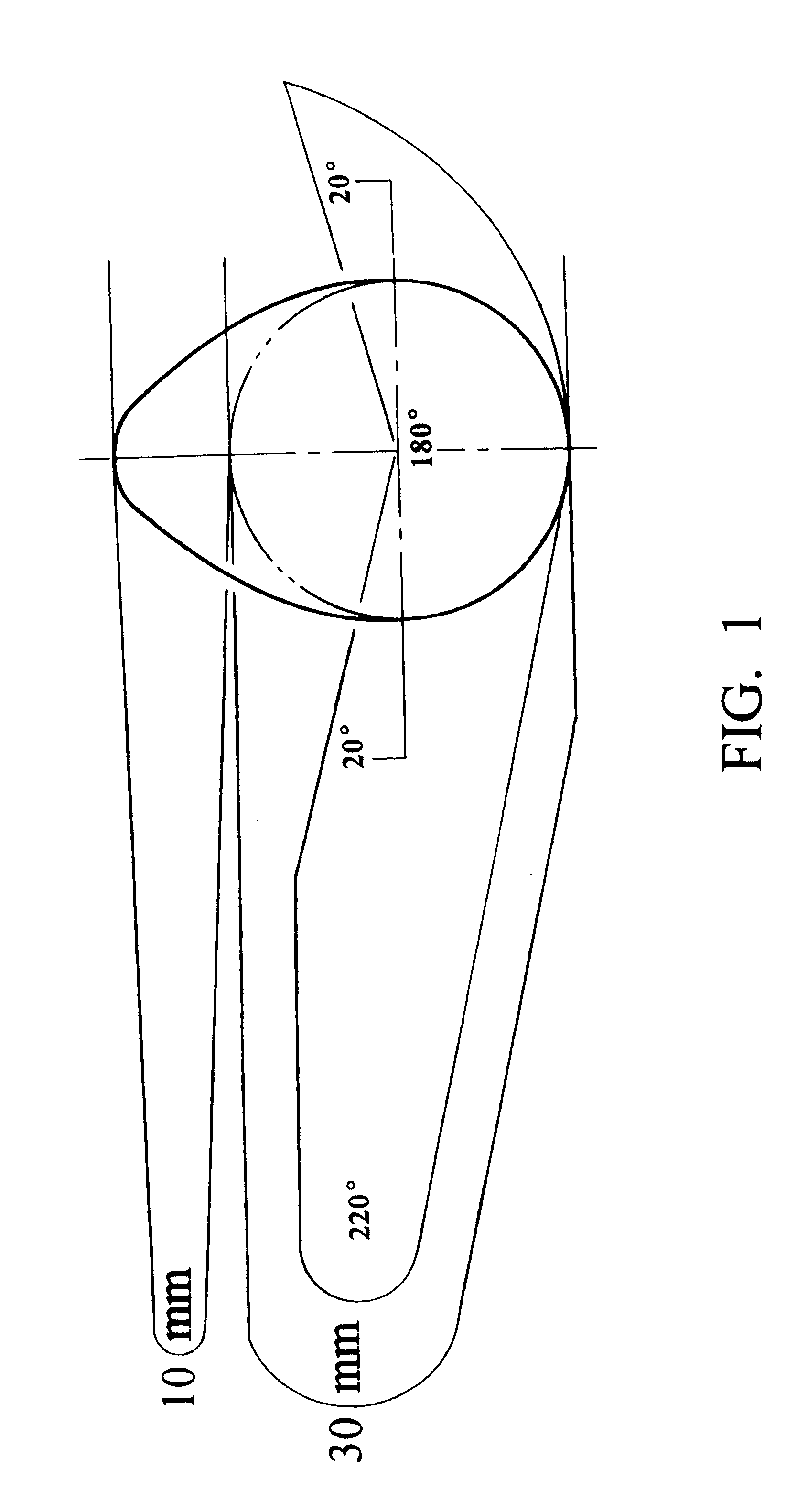
Thus, it is a general cam design technique to employ a displacement-time diagram in which the time axis is laid off in degrees of cam rotation. Displacements of the follower and periods of dwell are selected and indicated on the diagram and connected by suitable curves. Examples of curves are...


PUM

PropertyMeasurementUnit
camshaft rotationaaaaaaaaaa
diameteraaaaaaaaaa
diameteraaaaaaaaaa

Abstract

A cam system to generate valve actuation in an engine that includes a circular camlobe rotated about a first axis is described. The first axis is a preselected distance from the centerpoint of the circular camlobe. The cam system also includes a cam-follower that surrounds the camlobe and that has an inner oval surface with a major and minor axis. The inner oval surface is in moving contact with the circular camlobe during rotation of the camlobe.

Description

1. Field of the InventionThe invention relates in general to the field of engines, particularly to gasoline-type internal combustion engines, although it is also applicable to air compressors, gas, and diesel cycle engines. More specifically, the invention relates to cam systems used with internal combustion engines to vary the actuation, timing, duration, lift, and operation of valves.2. Background and Description of the Related ArtAn internal combustion engine burns fuel within one or more cylinders and converts the expansive force of combustion into a motive power able to do work. In an internal combustion engine for a vehicle (such an automobile or motorcycle), this process involves converting the combustion force into rotational force on the crankshaft which is then transferred to move the vehicle.Each cylinder of an internal combustion engine contains a reciprocating piston. The piston is contained within the cylinder in a tight-fit sliding arrangement that permits only a line...

Claims


Application Information

Patent Timeline
Patent Type & Authority Patents(United States)
IPC IPC(8): F01L1/00F01L13/00F01L1/30F01L1/34F01L1/18F01L3/20
CPCF01L1/185F01L1/30F01L3/20F01L13/0026F01L1/34Y10T29/49298F01L2820/035
Inventor LINEBARGER, TERRY GLYN
Owner LINEBARGER TERRY GLYN
Why Eureka
Try Eureka