Combustion plant and a method of combusting a fuel

a combustion plant and fuel technology, applied in the direction of combustion process, steam engine plant, lighting and heating apparatus, etc., can solve the problems of high investment cost per effect unit, complex hard treatment agent such as hydrogen sulphuric compound, and large plant area

Inactive Publication Date: 2001-07-17
GENERAL ELECTRIC TECH GMBH
View PDF7 Cites 7 Cited by
  • Summary
  • Abstract
  • Description
  • Claims
  • Application Information

AI Technical Summary

Problems solved by technology

Thereby, a complication is that the rest product obtained by the gasifying consists of a liquid glass-like slag with a temperature of approximately 1000.degree. C.
Another complication is that, if the gasifying is driven too far, not only volatile and non-problematic gases such as H.sub.2, CO, CO.sub.2 and H.sub.2 O are obtained in the combustible gas, but also more complicated and hard treated agents such as hydrogen sulphuric compounds.
This makes such a plant very extensive, space-demanding and makes the investment cost per effect unit become high.
Furthermore, the important complexity implies that the reliability and applicability of the plant is unsatisfactory at a lot of occasions.
Furthermore, the efficiency of such a plant becomes restricted due to the energy demanding measures required for different purifying stages, the oxygen gas needed for the gasifying and due to the rest product obtained still having a certain energy content.
However, it is a disadvantage to need to employ several different types of fuels for one and the same plant, as this complicates the handling and the operation of the plant.
A problem which has burdened the PFBC- as well as PCFB-technique and obstructed the obtaining of a very high efficiency is that the upper temperature limit at which a combustion of for instance coal in a fluidized bed takes place normally is approximately 850.degree. to 950.degree. C. depending on the coal quality.
However, as the combustion gases leaving the combustion chamber contain a significant amount of particles of ash, this high temperature obtained in the topping combustion chamber will result in a melting of ash, causing substantial problems in the gas turbine.
However, hot gas filters are expensive and have an unsatisfactory reliability.

Method used


Image

  • Combustion plant and a method of combusting a fuel
  • Combustion plant and a method of combusting a fuel
  • Combustion plant and a method of combusting a fuel

Examples


Embodiment Construction

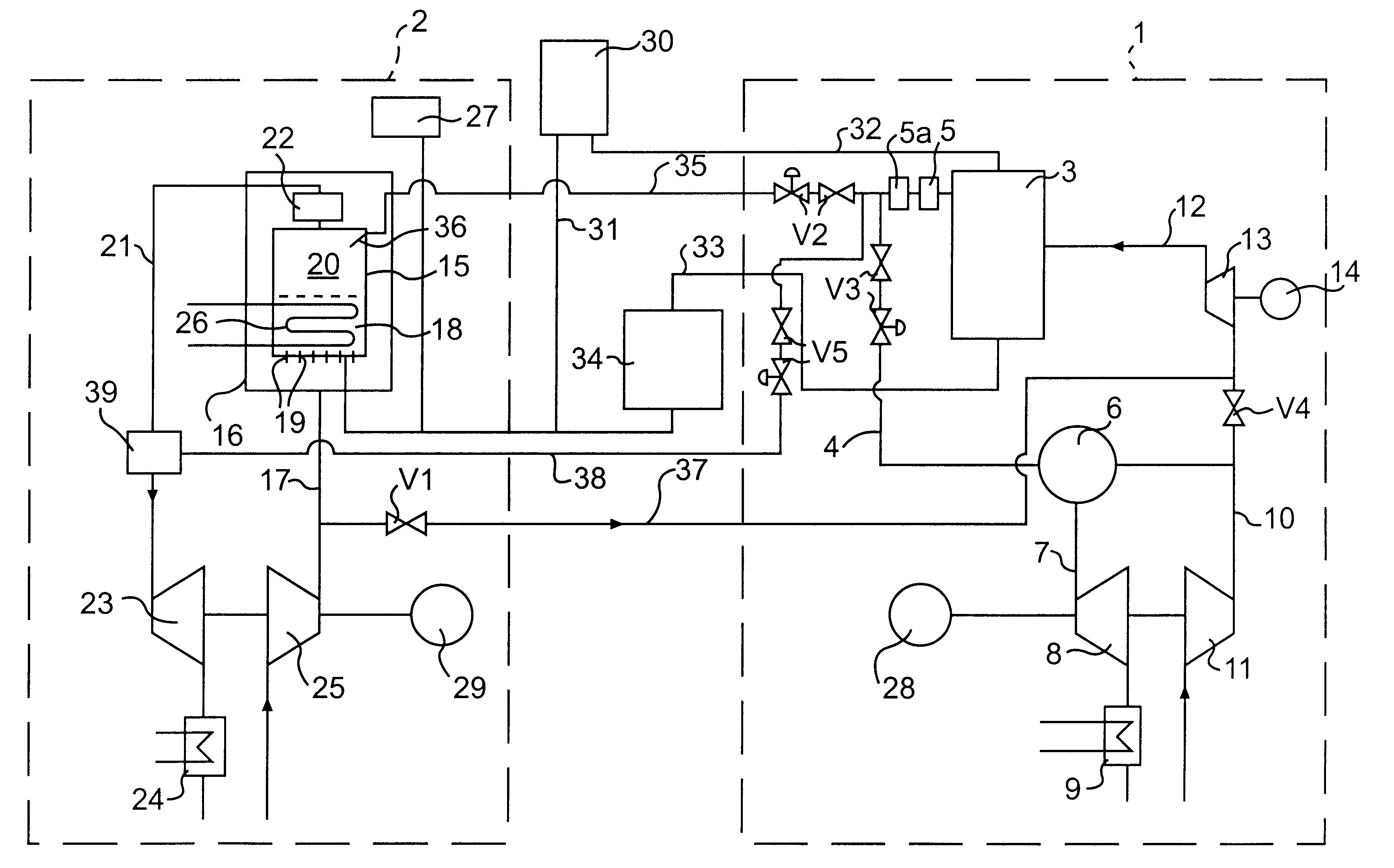
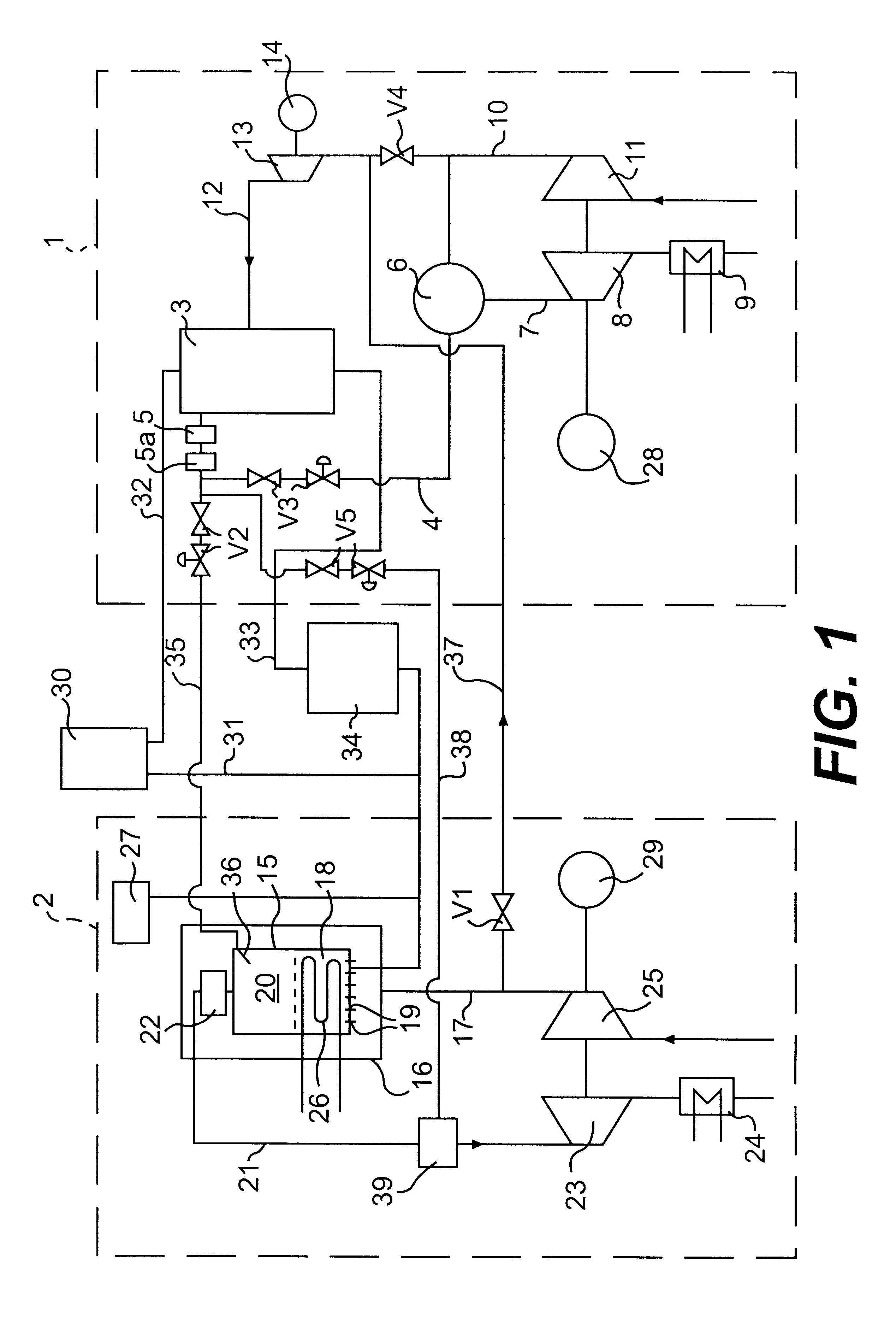
The combustion plant shown in FIG. 1 comprises a first combustion circuit 1 and a second combustion circuit 2. The first circuit 1 comprises a gasifying reactor 3 which is arranged to produce a combustible gas and a degassed combustible rest product from a fuel. The combustible gas is conducted through a gas conduit 4 to a heat exchanger 5 arranged to cool the combustible gas. The heat exchanger 5 may be connected to a steam circuit for generating or superheating steam for a steam turbine not shown. From the heat exchanger 5 the cooled combustible gas is conducted via a purifying equipment 5a, for instance in the shape of a filter, to a first combustion chamber 6. The first combustion chamber 6 is arranged to combust the combustible gas while producing hot combustion gases, and these gases are conducted through a combustion gas channel 7 from the first combustion chamber 6 to the atmosphere. The combustion gas channel 7 comprises first means for extracting energy from the combustion...


PUM


Abstract

A method of combusting a fuel, and a combustion plant are proposed. The combustion plant comprises a first circuit (1) with a gasifying reactor (3) to produce a combustible gas and a degassed, combustible rest product from the fuel. The combustible gas is supplied to a first combustion chamber (6) and there it is combusted while forming combustion gases. First means (8, 9) are arranged to take advantage of the energy in these gases. The plant further comprises a second circuit (2) with a second combustion chamber (15) which is supplied with the combustible rest product from the gasifying reactor (3). The rest product is combusted in the second combustion chamber (15) while forming combustion gases. The second circuit (2) further comprises second means (23, 24) for taking advantage of the energy of the combustion gases produced in the second circuit (2).

Description

THE BACKGROUND OF THE INVENTION AND PRIOR ARTThe present invention relates to a combustion plant comprising a first circuit with a gasifying reactor which is arranged to produce a combustible gas and a degassed combustible rest product from a fuel, a first combustion chamber which is arranged to enable combustion of the combustible gas while forming combustion gases, and first means which are arranged to take advantage of energy produced in the first combustion chamber. The invention also relates to a method of combusting a fuel.There are known combustion plants comprising a gasifying reactor in which a combustible gas is produced at substoichiometric combustion of a fuel. Such plants are employed for relatively delicate fuels, such as for example coal or waste. The combustible gas is supplied to a combustion chamber in which the gas is combusted while forming hot combustion gases which are employed to drive a gas turbine. Furthermore, such plants normally comprise an exhaust gas bo...

Claims


Application Information

Patent Timeline
Patent Type & Authority Patents(United States)
IPC IPC(8): F01K23/06F02C6/18F02C3/28F23C6/04F23C10/00F23C10/16
CPCF01K23/067F02C6/18Y02E20/18F23C10/00
Inventor JANSSON, SVEN AKYRKLUND, BENSJODIN, MATS
Owner GENERAL ELECTRIC TECH GMBH
Why Eureka
Try Eureka