Apparatus for generating a numerical control command according to cut resistance value and cut torque value of machining simulation

a numerical control and simulation technology, applied in computer control, program control, instruments, etc., can solve problems such as difficulty in continuing, excessive load on a tool or inappropriate surface roughness, deterioration of machining efficiency, etc., to improve machining techniques, improve machining efficiency, and prolong life

Inactive Publication Date: 2001-07-24
OKUMA CORP +3
View PDF29 Cites 101 Cited by
  • Summary
  • Abstract
  • Description
  • Claims
  • Application Information

AI Technical Summary

Benefits of technology

Furthermore, since accurate actual tool performance information can be generated, a user of the machine tool can, through analysis of the information, contribute to determination of machining conditions endurable for a long term unmanned operation, improvement of machining techniques for work shape accuracy enhancement and machined surface accuracy enhancement, and a tool manufacturer can also contribute to development of a tool with longer life and higher abrasion endurance which is appropriate for its customers' environment.

Problems solved by technology

As a result, when a machining process is moved from machining with a heavy machining load to machining with a light machining load, a feedrate is controlled to be slow regardless of the actually light machining load, which leads to deterioration in machining efficiency.
On the contrary, when a machining process is moved from machining with a light machining load to machining with a heavy machining load, a feedrate is controlled to be fast regardless of the actually heavy machining load, which leads to an excess load on a tool or inappropriate surface roughness.
As a consequence, it has been extremely difficult to continue cutting with an optimal feedrate or a cutting speed, which leads to earlier abrasion of a tool and deterioration in machining accuracy and surface roughness.
Moreover, when a tool hits a portion of a material to be machined with a rapidly increasing cut resistance value, damage easily occurs to the tool and to the material to be machined.
Information which would affect a tool life and machining accuracy, for example how an engagement angle of the tool has changed or which portion of the tool has had the heaviest load on it, has not been sufficiently obtained.
Therefore, it has been difficult to improve tool management techniques, machining techniques, and tool development techniques based on analysis of an effect of an ever-changing machining environment on a tool.

Method used


Image

  • Apparatus for generating a numerical control command according to cut resistance value and cut torque value of machining simulation
  • Apparatus for generating a numerical control command according to cut resistance value and cut torque value of machining simulation
  • Apparatus for generating a numerical control command according to cut resistance value and cut torque value of machining simulation

Examples


first embodiment

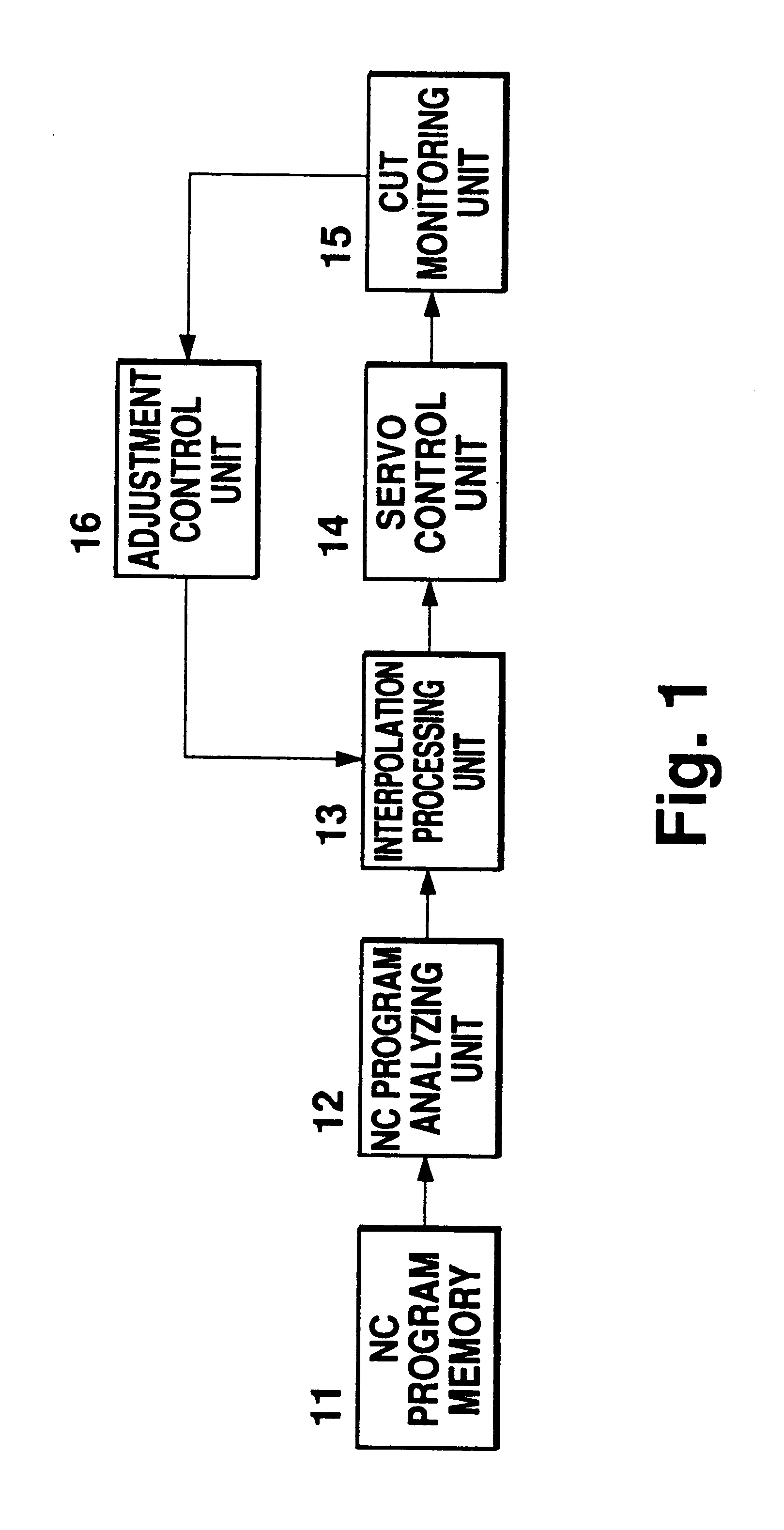
A first embodiment related to a machining simulation device and method of the present invention used in NC machining is a machining simulation device which performs a real time machining simulation based on shape data regarding a material and a tool, and performs in advance a numerical control command for controlling an interpolation speed or a motor torque value at an appropriate value based on a cut amount recognized through the simulation or a cut resistance value found by the cut amount.

Hereinafter, an embodiment example of feedrate control by the present machining simulation device used in NC machining after interpolation processing and an embodiment example wherein a motor torque correction by the present machining simulation device used in NC machining is incorporated by sending the correction to a current control unit used for servo control will be explained.

Hereinafter, explanation will be provided referring to a block diagram in FIG. 4.

In the block diagram in FIG. 4, block...

second embodiment

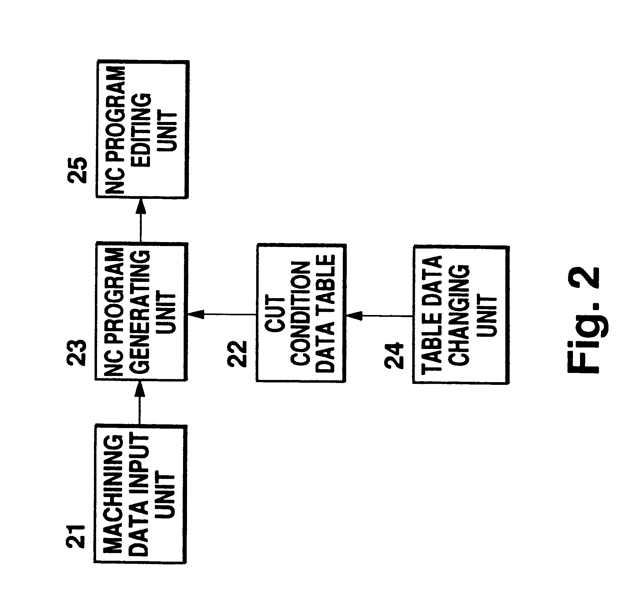
A second embodiment related to machining simulation device and method of the present invention used in NC machining is a machining simulation device which temporarily generates an NC program using machining data input by an operator, carries out machining simulation based on the NC program and material shape data, and carries out speed command determination in the NC program based on a cut amount recognized by the simulation or a cut resistance value obtained by the cut amount.

An example of the present machining simulation device used in NC machining separated from a numerical control device will be explained.

Hereinafter, explanation will be provided referring to a block diagram in FIG. 5.

In the block diagram in FIG. 5, blocks common to the block diagram in FIG. 2 have the same reference numbers, and block 25 is missing in FIG. 5. For blocks common to or similar to the blocks in FIG. 4, no common reference numbers are used, since the explanation of the blocks will be provided again ...

third embodiment

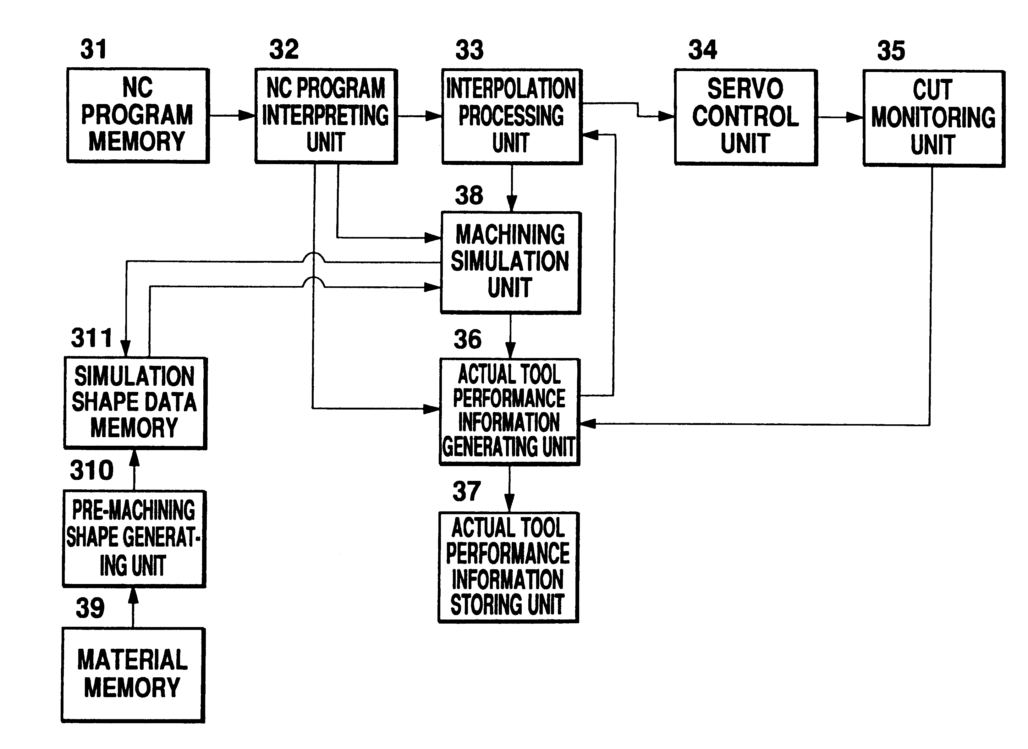
A third embodiment related to the machining simulation device and method of the present invention used in NC machining is a machining simulation device which performs a real time machining simulation based on material and tool shape data, and generates actual tool performance information based on data such as a cut amount recognized by the simulation and a tool portion used for cutting.

Hereinafter, an explanation will be provided referring to a block diagram in FIG. 6.

In the block diagram in FIG. 6, blocks common to the block diagram in FIG. 3 have the same reference numbers. For blocks common to or similar to the blocks in FIG. 4, no common reference numbers are used, since the explanation of the blocks will be provided again for the sake of easier comprehension.

An NC program which will be used for the up-coming machining is stored in an NC program memory 31.

An NC program interpreting unit 32 reads the NC program from the NC program memory 31 block by block, and interprets the bloc...


PUM


Abstract

A method of simulation of NC machining, wherein machining simulation is carried out according to blank shape data, tool shape data and an NC program to modify the NC program or interpolation data by feedforward control so that optimum cutting conditions can be obtained. The simulation result can be used for correcting the NC program and the interpolation data at the next stage. Further, a record of tools used can be generated on the basis of this simulation result.

Description

The present invention relates to a machining simulation device and method used in NC machining. More specifically, the present invention relates to a device and method for generating a numerical control command and actual tool performance information, based on machining simulation using data specifying material shape, tool shape, and machining shape.Referring to a block diagram in FIG. 1, an adjustment control command generating system used in a conventional numerical control system will be briefly explained hereinafter.In an NC program memory 11, an NC program which will be used for up-coming machining is stored.An NC program interpreting unit 12 reads the NC program in the NC program memory 11 block by block, and interprets the blocks. The NC program interpreting unit 12 sends to an interpolation processing unit 13 an interpolation kind, a target position, and a feedrate specified in the current block or specified prior to the current block as modal commands.The interpolation proc...

Claims


Application Information

Patent Timeline
Patent Type & Authority Patents(United States)
IPC IPC(8): G05B19/4069G05B19/406
CPCG05B19/4069G05B2219/35145G05B2219/50321G05B2219/43124G05B2219/41426B23Q15/00B23Q17/09
Inventor YAMAZAKI, KAZUOYAMAMOTO, KYOICHIMORITA, NAOKIMATSUMIYA, SADAYUKI
Owner OKUMA CORP
Why Eureka
Try Eureka