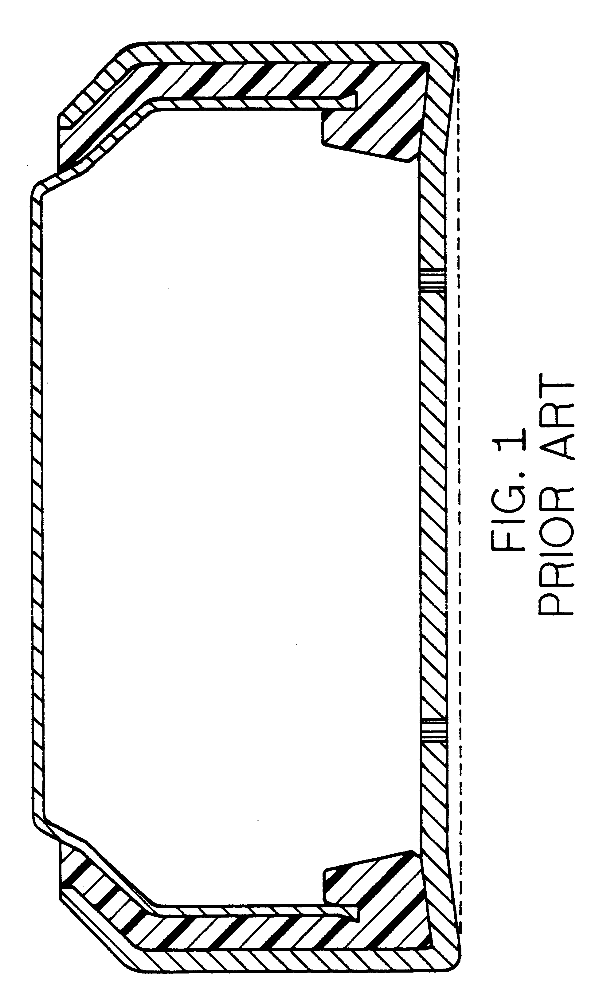
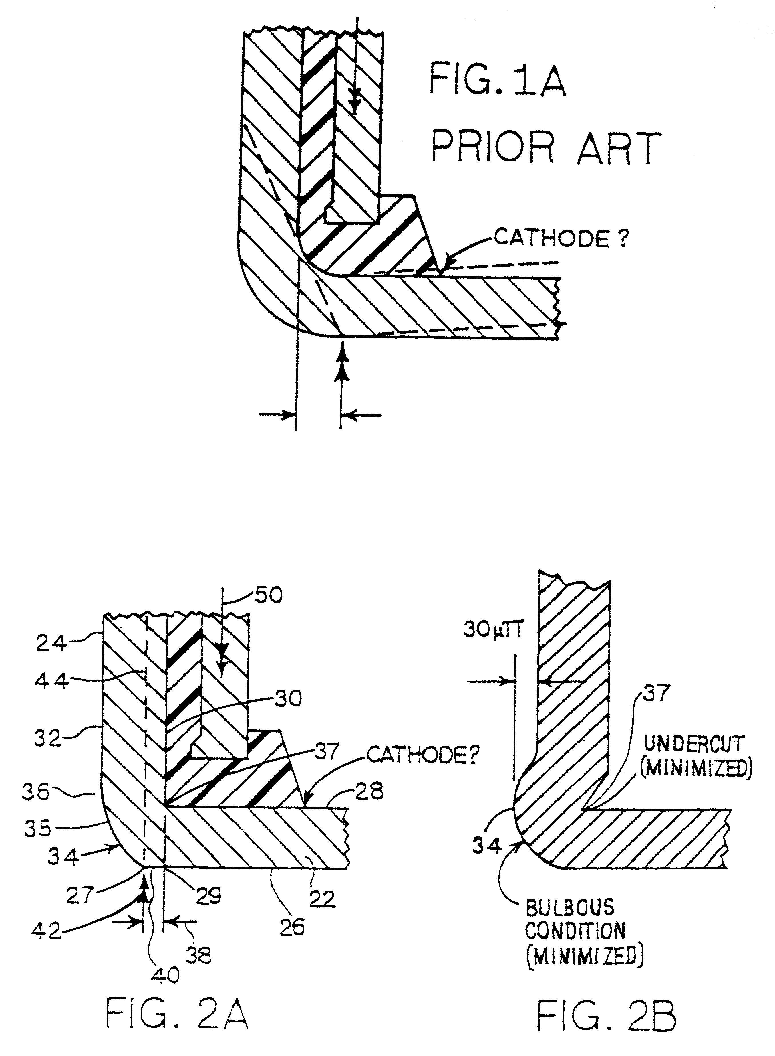
FIGS. 1 and 1A show a cross section of a prior art
assembly of a cathode can, an
anode can, and a seal. The dashed line in FIG. 1 represents a straight line across the cathode can between elements of the outer perimeter of outer surface of the bottom of the cathode can, which straight line would be coincident with a flat bottom on the cathode can. The
solid line next above the dashed line represents the actual outer surface of the bottom of the cathode can. FIG. 1 illustrates the phenomenon common in cells of the prior art, wherein the bottom of the cathode can is permanently displaced upwardly by the force used in joining the cathode and the
anode at final assembly of the
cell. Such displacement, of course, reduces the
usable volume inside the cell, with corresponding reduction in
total cell discharge capacity.
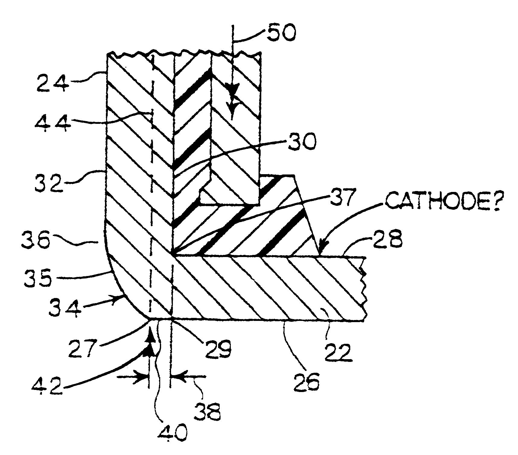
As the closing punch 46 exerts the force 42 indicated by arrows, thus urging the cathode can against the anode can and the seal, the cathode can is moved into the closing die 56 and against the transverse crimping lands 60 of the die. At the same time, the ejector punch 48 exerts its opposing force 50 against the anode. In order for the closing punch 46 to force the cathode can closed, it must exert sufficient force to form the
crimp on the distal edges 62 of the side wall 24, thus gripping anode can 54 and seal 16 in closure of the cell 10, as well as sufficient force to overcome the resistance of the opposing force 50 on the anode can.
The force 50 on the anode can has at least two purposes. First, the force 50 on the anode can helps stabilize the anode can while the cell is being closed. Second, and referring to FIG. 1A, the force 50 is exerted through seal 16 against the inner surface 28 of the bottom 22 of the cathode can, and thus generally opposes any
bending moment which may be imposed on the bottom 22 of the cathode can, thus tending to reduce the deformation suggested in FIG. 1A. The magnitude of the force 50 is generally determined with respect to the need to oppose the
bending moment, as the bulk of the force 42 on the cathode can can be absorbed by the stationary closing dies 56. Thus, to the extent the need to oppose
bending moment on the cathode can is reduced, the magnitude required of the force 50 on the anode can is correspondingly reduced.
The effectiveness of the force 50 in attenuating the tendency of the bottom of the cathode can to deform is related to the magnitudes of the respective forces 42 and 50, the lever arms over which they are applied relative to the respective can side walls, and the thickness of the material making up bottom 22. To the extent the thickness of the material is reduced, e.g. to correspondingly increase
usable interior volume, the contribution of the metal thickness to resisting bending forces is similarly reduced. Further, the lever arm between the anode can side wall and the cathode can side wall is also reduced when can wall thickness is reduced.
The retention of the flat configuration at the bottom of the can provides a corresponding increase in the useful volume inside the cell, which translates almost completely to an increase in space which can be filled with additional
reactive material.
FIG. 4 shows a perspective view of the cathode assembly used in cells representative of the present invention.
Active layer 66 is interposed between
barrier layer 68 and air
diffusion layer 70.
Active layer 66 ranges preferably between about 0.002 and about 0.05 inch thick; and facilitates the reaction between the hydroxyl in the
electrolyte and the cathodic
oxygen of the air.
Barrier layer 68 is a micro-porous plastic membrane about 0.001 inch thick, typically
polypropylene, having the primary function of preventing anodic
zinc particles from coming into physical contact with the remaining elements of the cathode assembly 18.
Barrier layer 68 however, does permit passage of hydroxyl ions and water therethrough. Air
diffusion layer 70 is preferably a micro-porous hydrophobic polymeric material such as a
polytetrafluoroethylene (PTFE) membrane about 0.004 inch thick, which permits passage of air therethrough. The air
diffusion layer 70 may be used to limit the
current density produced by the cell to a desired maximum. Air
diffusion layer 70 is further impervious to
battery electrolyte.

