

Imaging optical system
- Summary
- Abstract
- Description
- Claims
- Application Information
AI Technical Summary
Benefits of technology
Problems solved by technology
Method used
Image

Examples
first embodiment
[First Embodiment]
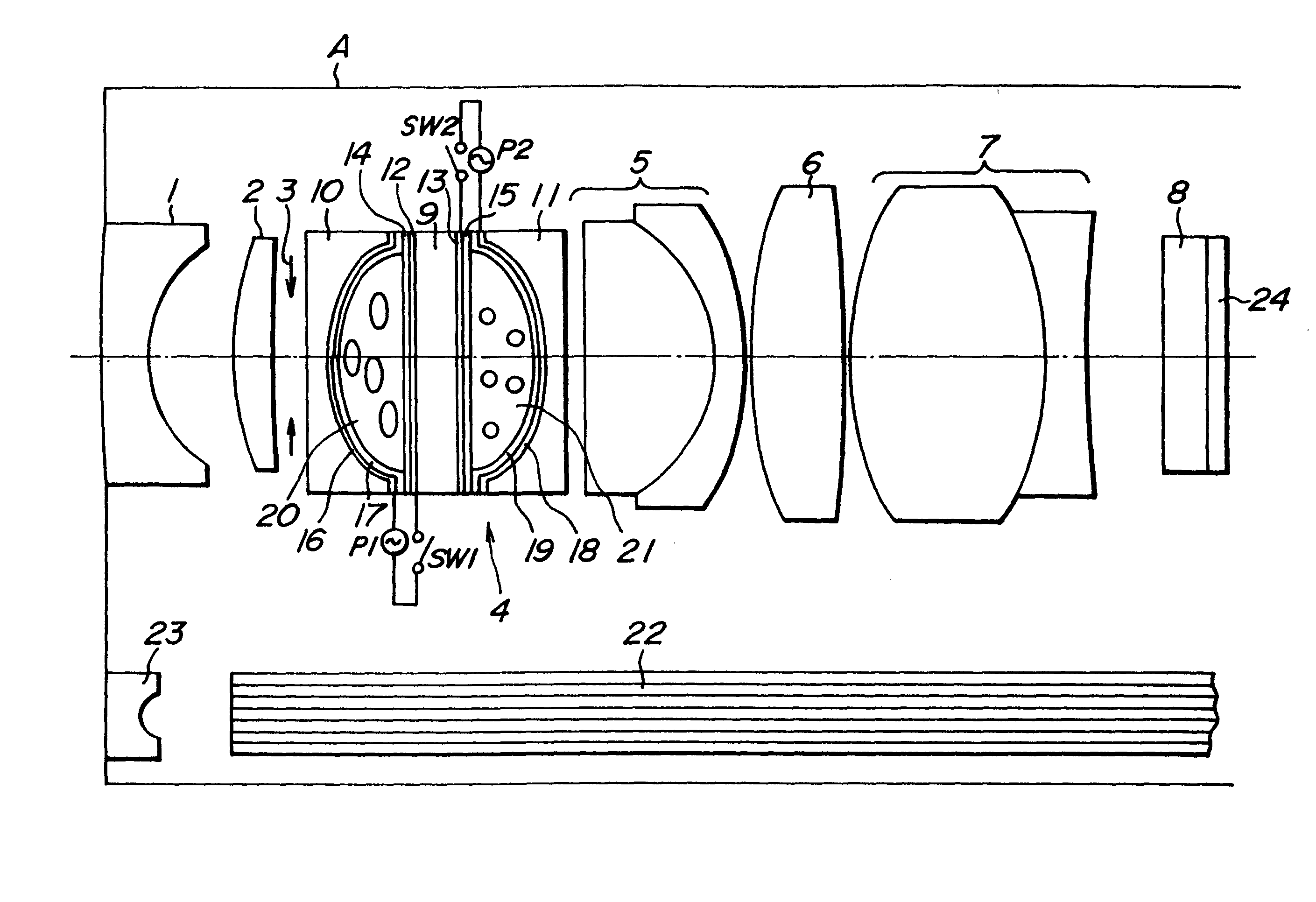
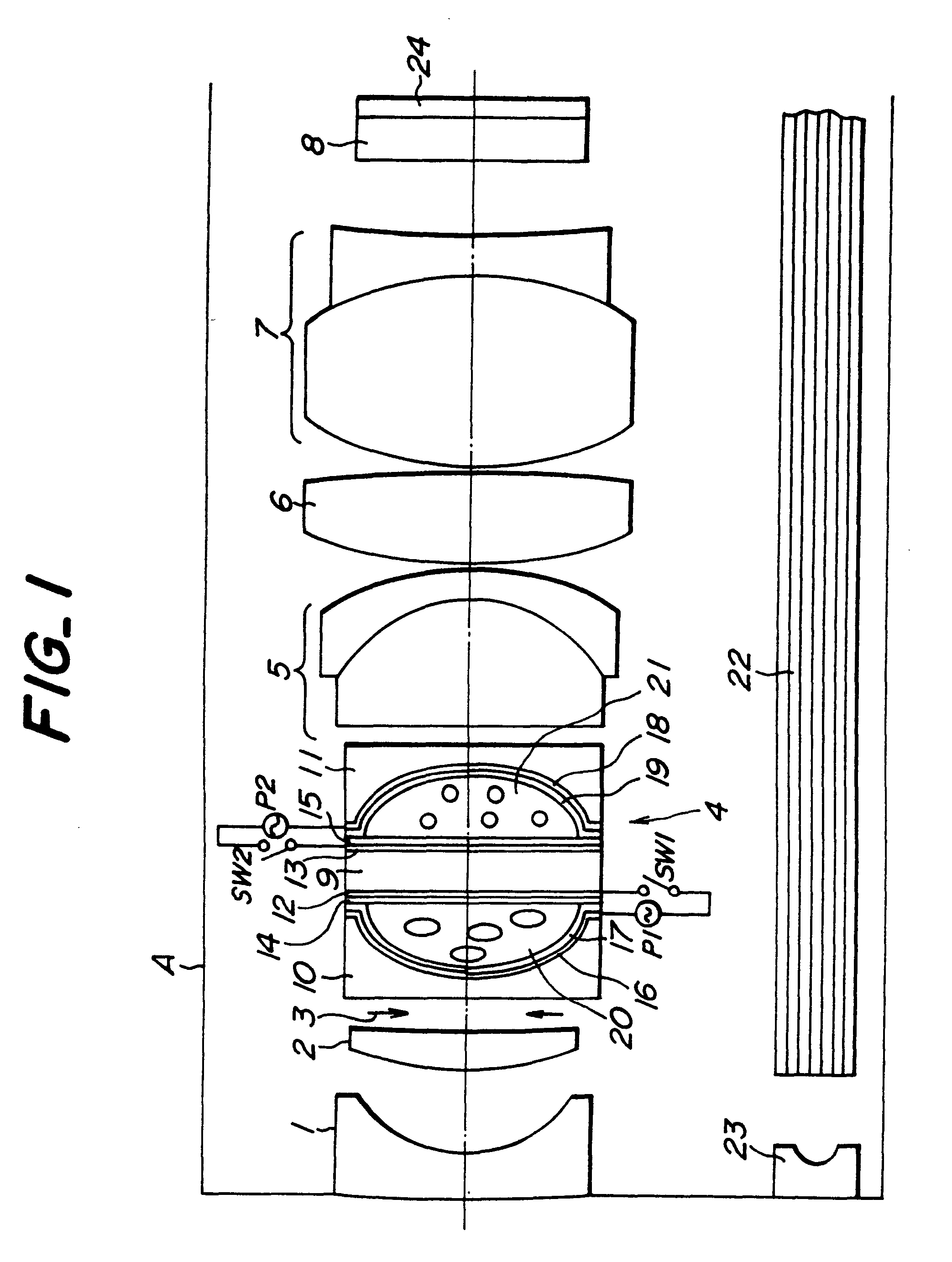
(1) Numerical value of optical system (As to definition of respective numerical value, refer to FIG. 7)
In this case, the refraction index of the nematic liquid crystal layer to be used at the ordinary ray is 1.52, the refraction index at the extraordinary ray is 1.76, the aperture diameter of the aperture diaphragm is 1.2 mm.
(2) Numerical value in case of applying the voltage on the nematic liquid crystal layer of the optical system.
n.sub.a =1.52
OB=18.3 (mm)
F.sub.NO =2.795
n.sub.b =1.52
f=1.4722 (mm)
IH=1.135 (mm)
(3) Numerical value in case of performing incidence of the polarized light having oscillating direction parallel to the major axis direction of liquid crystal molecule, under the state of applying voltage on the nematic liquid crystal of the optical system.
n.sub.a =1.76
OB=8 (mm)
F.sub.NO =2.78
n.sub.b =1.52
f=1.462 (mm)
IH=1.135 (mm)
(4) Numerical value in case of performing incidence of the polarized light having oscillating direction perpendicular to the major a...
second embodiment
[Second Embodiment]
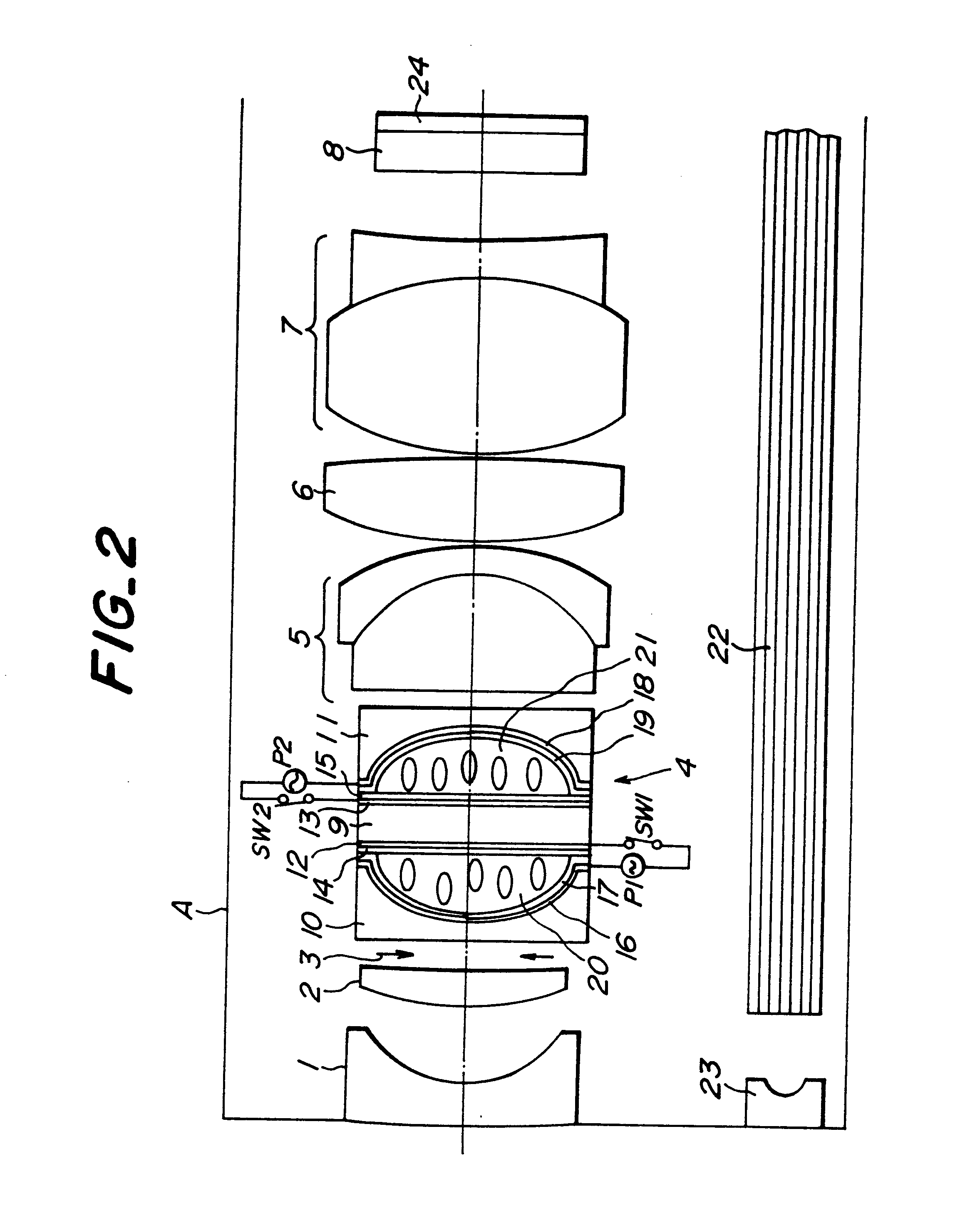
(1) Numerical value of optical system (As to definition of respective numerical value, refer to FIG. 8)
In this case, the refraction index of the nematic liquid crystal layer to be used at the ovary ray is 1.52, the refraction index at the extraordinary is 1.76, the aperture diameter of the aperture d is 1.4 mm.
(2) Numerical value in case of applying the voltage on the nematic liquid crystal layer of the optical system.
n.sub.a =1.52
OB=15.0 (mm)
F.sub.NO =7.39
n.sub.b =1.52
f=1.609 (mm)
IH=1.63 (mm)
(3) Numerical value in case of performing incidence of the polarized light having oscillating direction parallel to the major axis direction of liquid crystal molecule, under the state of applying voltage on the nematic liquid crystal of the optical system.
n.sub.a =1.76
OB=8 (mm)
F.sub.NO =7.37
n.sub.b =1.52
f=1.570 (mm)
IH=1.63 (mm)
(4) Numerical value in case of performing incidence of the polarized light having oscillating direction perpendicular to the major axis direction of l...
third embodiment
[Third Embodiment]
(1) Numerical value of optical system (As to definition of respective numerical value, refer to FIG. 8)
In this case, the refraction index of the nematic liquid crystal layer to be used at the ordinary ray is 1.52, the refraction index at the extraordinary ray is 1.76, the aperture diameter of the aperture diaphragm is 0.54 mm.
(2) Numerical value in case of applying the voltage on the nematic liquid crystal layer of the optical system.
n.sub.a =1.52
OB=15.0 (mm)
F.sub.NO =7.39
n.sub.b =1.52
f=1.608 (mm)
IH=1.63 (mm)
(3) Numerical value in case of performing incidence of the polarized light having oscillating direction parallel to the major axis direction of liquid crystal molecule, under the state of applying no voltage on the nematic liquid crystal of the optical system.
n.sub.a =1.76
OB=8 (mm)
F.sub.NO =7.37
n.sub.b =1.52
f=1.571 (mm)
IH=1.63 (mm)
(4) Numerical value in case of performing incidence of the polarized light having oscillating direction perpendicular to the major a...
PUM
 Abstract
Description
Claims
Application Information