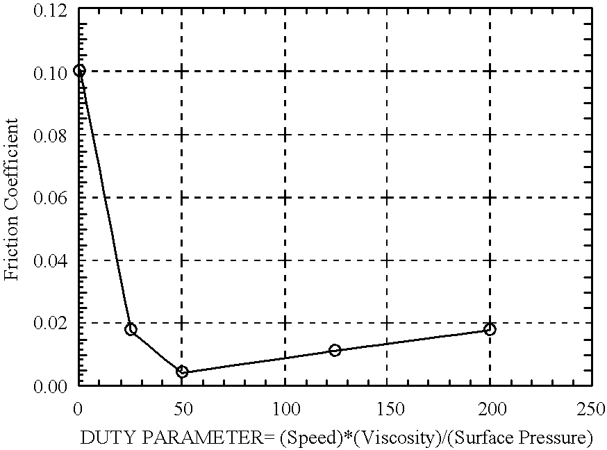
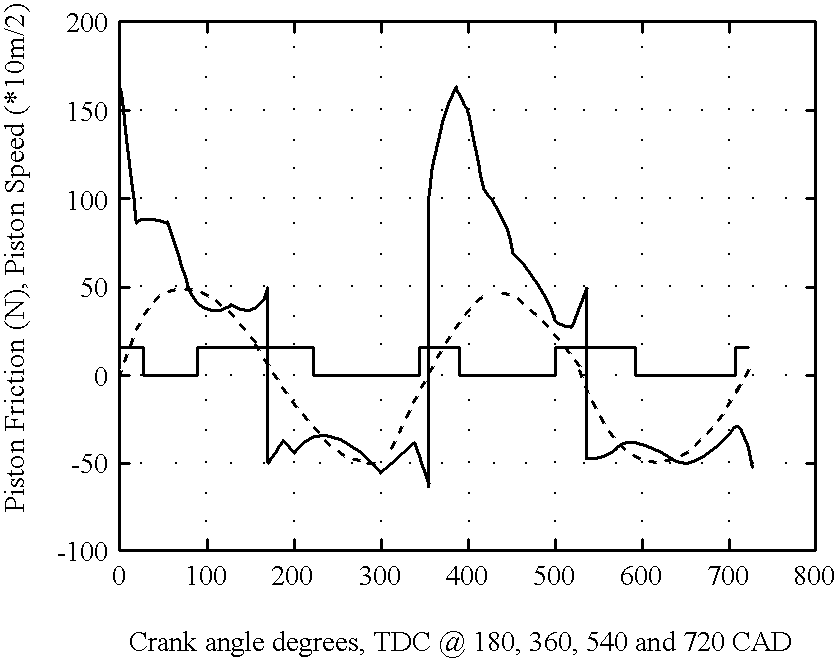
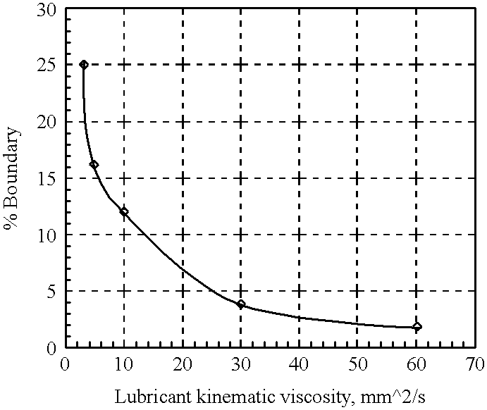
The invention is directed to an
internal combustion engine having one rotating sleeve per cylinder that is supported by two journal bearings. The objective of the rotation is to maintain the sliding motion between the piston rings and liner in order to maintain the hydrodynamic lubrication regime throughout the
stroke. The rings will be held stationary by the friction between the piston grooves and rings. However, if necessary, the rings can be pinned on the piston to prevent their rotation. Unlike the typical
sleeve valve engine, the surface area where tight tolerances between the sleeve and the block exist are confined to the minimum necessary for reliable hydrodynamnic support of the sleeve, minimizing the friction due to liner rotation. The intake of the fresh charge (or
fresh air in the case of a Diesel) and exhaust of the
combustion products are accomplished via conventional popper valve arrangement. A
flange on the upper part of the liner transfers the thrust loads to the
cylinder head and the block. Furthermore, the flange reinforces the upper part of the sleeve preventing or minimizing the sleeve expansion due to high
cylinder pressure that occurs when the piston is in proximity to
top dead center (TDC) which could otherwise take up the clearance of the upper journal bearing. This has been reported by Ricardo to be a typical phenomenon in
sleeve valve engines without a flange, causing a serious penalty in friction and wear between the sleeve and the block. A set of pressure activated sealing devices are installed on the upper part of the sleeve to prevent
high pressure combustion gases from entering the space between the liner and the block. The journal bearings that support the sleeve are supplied with pressurized oil from the
oil pump lubricating the bearings.
Lubricant leakage from these journal bearings fills up the space between the liner and the block and also lubricates the sealing devices on the upper part of the sleeve and the flange which acts as
thrust bearing. The excess
lubricant is removed by oil return passages and by direct leakage back to the oil pan. The oil that surrounds the liner will remove
excess heat from the engine, and may be used as the sole
coolant fluid of the engine. In fact, the motion of the liner will enhance
heat transfer from the liner to the oil.
The sleeve speed can be constant (for simplicity) or with alternating value (without reversal) for friction optimization. In the latter embodiment, the objective of alternating the value of the sleeve rotation is that at the mid portion of the
stroke, the piston speed is sufficient for hydrodynamic lubrication regardless of liner rotation. Therefore, liner rotation at that part of the cycle does not offer any significant frictional benefits as at around the dead centers. Thus, minimizing the rate of rotation will reduce the additional friction caused by the liner rotation. However, even at mid
stroke, a minimum rotational speed of the sleeve will have to be retained (even when the piston is at its peak speed) in order to retain the hydrodynamic
oil film in the journal bearings with some small expense in friction. Then, as the pistons slow down, the driving mechanisms will gradually accelerate the sleeves. When the pistons come to a fall stop, the sleeves will be at their peak speed. Then as the pistons speed up again, the sleeves could gradually slow down at their minimum speed when the pistons are at their maximum. An eccentric driving mechanism or a geartain based on the "Geneva Wheel" achieves this motion. The
kinetic energy stored in the sleeves at peak angular speed will return to the
system during deceleration. In a multi-
cylinder engine, the sleeves could be driven by independent mechanisms. However, gears installed on the outside of the sleeve surface (either the top or the bottom) could mesh with the sleeves of neighboring cylinders eliminating the need for individual driving mechanisms. The above driving method is particularly attractive if the constant sleeve speed embodiment is chosen, or if the alternating sleeve speed is to be used on a four
cylinder engine (or in any in-line engine with a flat
crankshaft design) where all pistons reach a dead center at the same time. In the latter case, the alternating magnitude rotation needs to be created by one mechanism and the motion will be duplicated from liner to liner.


